


7-3
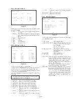
4. Checking Component Video Output R-Y
(MB-84 board)
<Purpose>
This checks component video output R-Y. If it is incorrect, cor-
rect colors will not be displayed when connected to, for instance,
projector.
Mode
Video Encoder (IC252) check in test
mode menu “0” Syscon Diagnosis
Signal
Color bars
Test point
COMPONENT VIDEO OUT (R-Y)
connector (75
Ω
terminated)
Instrument
Oscilloscope
Specification
700 ± 30 mVp-p
Checking method:
1) Confirm that the R-Y level is 700 ± 30 mVp-p.
Figure 7-5
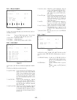
5. Checking Component Video Output Y
(MB-84 board)
<Purpose>
This checks component video output Y. If it is incorrect, correct
brightness will not be attained when connected to, for instance,
projector.
Mode
Video Encoder (IC252) check in test
mode menu “0” Syscon Diagnosis
Signal
Color bars
Test point
COMPONENT VIDEO OUT (Y)
connector (75
Ω
terminated)
Instrument
Oscilloscope
Specification
1 ± 0.05 Vp-p
Checking method:
1) Confirm that the Y level is 1 ± 0.05 Vp-p.
Figure 7-6
700 ± 30 mVp-p
1 ± 0.05 Vp-p
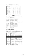
6. Checking RGB Output R
(MB-84 board) (AEP, UK model)
<Purpose>
This checks RGB output R. If it is incorrect, pictures will not be
displayed correctly in spite of connection to the TV with an EURO
AV connecting cord.
Mode
Video Encoder (IC252) check in test
mode menu “0” Syscon Diagnosis
Signal
Color bars
Test point
EURO AV 1 (RGB)-TV connector
!∞
pin (75
Ω
terminated)
Instrument
Oscilloscope
Specification
700 ± 30 mVp-p
Checking method:
1) Confirm that the R level is 700 ± 30 mVp-p.
Figure 7-7
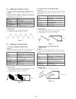
7. Checking RGB Output G
(MB-84 board) (AEP, UK model)
<Purpose>
This checks RGB output G. If it is incorrect, pictures will not be
displayed correctly in spite of connection to the TV with an EURO
AV connecting cord.
Mode
Video Encoder (IC252) check in test
mode menu “0” Syscon Diagnosis
Signal
Color bars
Test point
EURO AV 1 (RGB)-TV connector
!¡
pin (75
Ω
terminated)
Instrument
Oscilloscope
Specification
700 ± 30 mVp-p
Checking method:
1) Confirm that the G level is 700 ± 30 mVp-p.
Figure 7-8
700 ± 30 mVp-p
700 ± 30 mVp-p
Содержание DVP-S7700
Страница 11: ...1 1 SECTION 1 GENERAL DVP S7700 This section is extracted from AEP UK model instruction manual 3 864 941 31 ...
Страница 12: ...1 2 ...
Страница 13: ...1 3 ...
Страница 14: ...1 4 ...
Страница 15: ...1 5 ...
Страница 16: ...1 6 ...
Страница 17: ...1 7 ...
Страница 18: ...1 8 ...
Страница 19: ...1 9 ...
Страница 20: ...1 10 ...
Страница 21: ...1 11 1 11 E ...
Страница 36: ...DVP S7700 4 3 4 4 4 1 FRAME SCHEMATIC DIAGRAM 1 2 FRAME 1 2 ...
Страница 37: ...DVP S7700 4 5 4 6 FRAME SCHEMATIC DIAGRAM 2 2 FRAME 2 2 ...
Страница 39: ...DVP S7700 4 9 RF SERVO TK 47 DVP S7700 1 669 298 05 13 13 TK 47 BOARD SIDE B A B C D E F G H 1 2 3 4 5 6 ...
Страница 41: ...DVP S7700 4 13 4 14 TK 47 RF SERVO 2 SCHEMATIC DIAGRAM Ref No TK 47 board 3 000 series RF SERVO 2 TK 47 2 2 ...
Страница 71: ...DVP S7700 4 73 4 74 FP 75 FL DRIVER SCHEMATIC DIAGRAM Ref No FP 75 board 1 000 series FL DRIVER FP 75 ...