


6-7
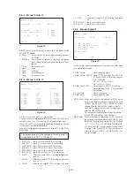
(9-7) MPEG Audio Analog Output
ROM audio data
→
ARP (IC806)
→
AV Decoder (IC203)
→
2ch
DAC (IC215)
→
Analog audio output
Error 10: ARP (IC806)
→
AV Decoder (IC203) data transfer er-
ror
35: 2ch DAC (IC215) serial transfer interruption is not de-
tected
37: PLL DAC (IC209) serial transfer interruption is not de-
tected
MPEG-audio bit stream data stored in ROM (IC803) are trans-
ferred to the AV Decoder (IC203) via ARP (IC806), and analog
audio data are output from 2ch DAC (IC215).
If no error is found, the message is displayed to prompt for key
entry.
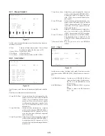
(9-8) Dual DAC (Serial)
ROM audio data
→
ARP (IC806)
→
AV Decoder (IC203)
→
2ch
DAC (IC215)
→
Analog audio output (Attenuation)
Error 10: ARP (IC806)
→
AV Decoder (IC203) data transfer er-
ror
35: 2ch DAC (IC215) serial transfer interruption is not de-
tected
37: PLL DAC (IC209) serial transfer interruption is not de-
tected
MPEG-audio bit stream data stored in ROM (IC803) are trans-
ferred to the AV Decoder (IC203) via ARP (IC806), and they are
attenuated by 12dB (-12dB) in the 2ch DAC (IC215), then analog
audio data are output.
If no error is found, the message is displayed to prompt for key
entry.
(9-9) Audio Mute Line
ROM audio data
→
ARP (IC806)
→
AV Decoder (IC203)
→
Ana-
log audio output (Mute)
Error 10: ARP (IC806)
→
AV Decoder (IC203) data transfer er-
ror
35: 2ch DAC (IC215) serial transfer interruption is not de-
tected
37: PLL DAC (IC209) serial transfer interruption is not de-
tected
MPEG-audio bit stream data stored in ROM (IC803) are trans-
ferred to the AV Decoder (IC203) via ARP (IC806), and analog
audio data are output from 2ch DAC (IC215).
In such a case, first the mute by I/O of SH (IC805), then the mute
by setting AV Decoder (IC203), and by setting DAC are turned on
respectively to output low frequency tones.
Finally, the mute is turned off to output high frequency tones.
Checking is finished when high frequency tones are heard.
Low tones will be heard before this checking finished, if the mute
is not effective.
To make sure which mute is not effective, the check should be
repeated while paying attention to the message.
If no error is found, the message is displayed to prompt for key
entry.
g
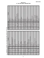
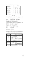
Error Codes in Diagnostic Test
01: Mode not supported is selected
02: Reset error
03: Data write error
04: Data read error
05: Write/read data mismatch error
06: DMA transfer DREQ error
07: DMA transfer address error
10: Chip-to-chip data transfer error
11: Serial transfer error
12: EEPROM (IC801) is not ready
13: DSP (IC506) data is not ready
14: DSP (IC506) download error
21: ARP (IC806) interruption is not detected
22: Decrypt (IC811) interruption is not detected
31: AV Decoder (IC203) interruption is not detected
32: Servo DSP interruption is not detected
33: SSI interruption is not detected
34: DNR (IC251) interruption is not detected
35: 2ch DAC (IC215) interruption is not detected
36: EEPROM (IC801) interruption is not detected
37: PLL DAC (IC209) interruption is not detected
40: Video Encoder (IC252) ID error
41: Vsync interruption is not detected
42: Vsync interrupt cycle error
53: Video Encoder (IC252) interruption is not detected
90: Judged as error by inspector
91: Check of this item is quitted by key entry
92: Check of all items is quitted by key entry
93: Interruption by time over
99: Other errors
Содержание DVP-S7700
Страница 11: ...1 1 SECTION 1 GENERAL DVP S7700 This section is extracted from AEP UK model instruction manual 3 864 941 31 ...
Страница 12: ...1 2 ...
Страница 13: ...1 3 ...
Страница 14: ...1 4 ...
Страница 15: ...1 5 ...
Страница 16: ...1 6 ...
Страница 17: ...1 7 ...
Страница 18: ...1 8 ...
Страница 19: ...1 9 ...
Страница 20: ...1 10 ...
Страница 21: ...1 11 1 11 E ...
Страница 36: ...DVP S7700 4 3 4 4 4 1 FRAME SCHEMATIC DIAGRAM 1 2 FRAME 1 2 ...
Страница 37: ...DVP S7700 4 5 4 6 FRAME SCHEMATIC DIAGRAM 2 2 FRAME 2 2 ...
Страница 39: ...DVP S7700 4 9 RF SERVO TK 47 DVP S7700 1 669 298 05 13 13 TK 47 BOARD SIDE B A B C D E F G H 1 2 3 4 5 6 ...
Страница 41: ...DVP S7700 4 13 4 14 TK 47 RF SERVO 2 SCHEMATIC DIAGRAM Ref No TK 47 board 3 000 series RF SERVO 2 TK 47 2 2 ...
Страница 71: ...DVP S7700 4 73 4 74 FP 75 FL DRIVER SCHEMATIC DIAGRAM Ref No FP 75 board 1 000 series FL DRIVER FP 75 ...