


– 7 –
5.
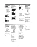
REPLACING OPTICAL PICK-UP
5-1.
Handling
1) A red laser diode for DVD requires more attention to static
electricity than general infrared laser diodes for CD.
Because its durability to static electricity is far weaker than
that of infrared laser diodes, always use an earth band when
handling the optical pick-up block as service parts.
2) As for the flexible board KHS-180A (RP) packed as service
parts, the short lands have been soldered to protect from static
electricity. Accordingly, remove solders when replacing opti-
cal pick-up. (See Fig. 6)
Fig. 6 Flexible board
3) In handling the KHS-180A (RP), do not touch inhibited parts
shown in Fig. 7, but grip the slide base bearing and U-shaped
guide.
Fig. 7 KHS-180A (RP)
DVD short land
CD short land
Slide base bearing
Skew sensor
Lens actuator
covers
Objective lenses
U-shaped guide
OEIC
Laser holder
Flexible board
Connector
Laser coupler
Touch inhibited parts
• Objective lens
• Skew sensor
• Laser holder
• Laser coupler
• Flexible board
• OEIC
• Lens actuator covers
Содержание DVP-S7700
Страница 11: ...1 1 SECTION 1 GENERAL DVP S7700 This section is extracted from AEP UK model instruction manual 3 864 941 31 ...
Страница 12: ...1 2 ...
Страница 13: ...1 3 ...
Страница 14: ...1 4 ...
Страница 15: ...1 5 ...
Страница 16: ...1 6 ...
Страница 17: ...1 7 ...
Страница 18: ...1 8 ...
Страница 19: ...1 9 ...
Страница 20: ...1 10 ...
Страница 21: ...1 11 1 11 E ...
Страница 36: ...DVP S7700 4 3 4 4 4 1 FRAME SCHEMATIC DIAGRAM 1 2 FRAME 1 2 ...
Страница 37: ...DVP S7700 4 5 4 6 FRAME SCHEMATIC DIAGRAM 2 2 FRAME 2 2 ...
Страница 39: ...DVP S7700 4 9 RF SERVO TK 47 DVP S7700 1 669 298 05 13 13 TK 47 BOARD SIDE B A B C D E F G H 1 2 3 4 5 6 ...
Страница 41: ...DVP S7700 4 13 4 14 TK 47 RF SERVO 2 SCHEMATIC DIAGRAM Ref No TK 47 board 3 000 series RF SERVO 2 TK 47 2 2 ...
Страница 71: ...DVP S7700 4 73 4 74 FP 75 FL DRIVER SCHEMATIC DIAGRAM Ref No FP 75 board 1 000 series FL DRIVER FP 75 ...