


6-12
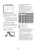
## Version Information ##
IF con.
Ver : x. xxx (xxxx)
Group 00
SYScon.
Ver : x. xxx (xxxx)
Model xx
Region 0x
Servo DSP. Ver : 1. xxxx
OPT Type : x LASER
Exit: RETURN
_
6-8. VERSION INFORMATION
The ROM version, region code, OPT type, etc. are displayed if
[5]
is selected in the Test Mode Menu. The parenthesized
hexadecimal number in the version number field indicates the
checksum value of the ROM.
Note : After down loading ROM data, sometimes it happens that
checksum is not the same as that of ROM data which has
been down loaded. In such a case, go back to the menu
and select “0. Syscon Diagnosis”, then select “1. All” in
“2. Version”. If the result of this operation does not give
an agreement, it must be either Down Load error or ROM
error.
6-9. VIDEO LEVEL ADJUSTMENT
On the Test Mode Menu screen, selecting
[6]
displays color bars
for video level adjustment. During display of color bars, OSD
disappears but the menu screen will be restored if pressing any
key.
Measurement point:
LINE OUT (VIDEO) connector (75
Ω
terminated)
Measuring instrument: Oscilloscope
Adjustment device:
RV501 on MB-99 board
Specified value:
1.0
+0.04
Vp-p
–0.02
6-10. IF CON Function Check Mode
1. Button function
When any button except
[POWER]
of the main unit is pressed in
the Test mode, the unit exits from the Self Check mode of the
fluorescent display tube.
While a button is pressed, the function name of that button is
displayed on the FLD, and when stops pressing the button,
“Nothing” is displayed. When two buttons are pressed
simultaneously, “DOUBLE” is displayed. As for the name of the
button refer to the following table.
For the button with LED, whenever it presses, turning on the light
and turning off are repeated.
Port
Number Function Key
Input Voltage Detection Range
Name
Code
MIN
TYP
MAX
SW1
0
POWER
00
0.00
—
1.10
34p
1
PREV
0B
1.11
1.65
2.20
SW2
0
EJECT
09
0.00
—
1.10
35p
SW3
0
PLAY
0A
0.00
—
1.10
36p
1
PAUSE
02
1.11
1.65
2.20
SW4
0
STOP
01
0.00
—
1.10
37p
1
NEXT
0C
1.11
1.65
2.20
The direction buttons on the remote commander are functioned as
buttons to entering the specific mode.
:
Fluorescent display Grid check
:
LED check (Not used)
:
All lights up
:
Fluorescent display Anode check
All buttons are judged with the voltage of A/D port. The reference
voltage of A/D port is EVER +3.3 V. To reject chattering,
measure the voltage twice and the same values are obtained, this
voltage is judged as the A/D port voltage. The dead zone is
provided for the IF CON button judgment voltage. When a
voltage within the range of dead zone is input, “IGNORE” is
displayed.
2. Remote commander receiving function
If the unit is received a command of the remote commander when
“NOTHING” is displayed, the function name of the code of the
remote commander is displayed on the display. The code which
the unit can receive is only DVD category.
The
[DISPLAY]
button on the remote commander functions as
switch of the button name display and code display. In the code
display mode, “REM NO.xx” is displayed. The received code is
displayed with hexadecimal notation into the “xx” column. When
the unit has not received the command, “FF” is displayed.