


5-53
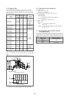
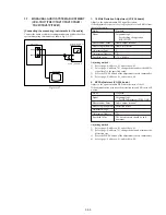
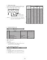
1. 1.5 MHz Deviation Adjustment (VC-234 board)
Sets the spectrum of the L-ch ((L+R)/2 signal) level modulated
during recording. If deviated, the crosstalk signal of the audio signal
will occur and the audio level will drop during both playback and
recording.
Mode
VTR recording
Signal
Input the AFM DEV jig output signal to
the left and right audio input terminal
Measurement Point
CH1: AFM DEV jig TP31
CH2: AFM DEV jig TP3
Measuring Instrument
Oscilloscope
ADD mode
CH2 INV mode
Adjustment Page
F
Adjustment Address
7B
Specified Value
The level difference between CH1 signal
and CH2 signal should be minimum.
Connection:
1)
Connect TP24, TP25 and TP26 of the AFM DEV jig to CN982
of the VC-234 board.
TP24(GND) ................ Pin
8
of CN982
TP25(REC RF) ........... Pin
5
of CN982
TP26(RF SWP) .......... Pin
qa
of CN982
2)
Connect the audio output terminal (J1 and J2) of the AFM DEV
jig to AUDIO terminal of the unit.
3)
Connect TP28(DC), TP27(GND) of the AFM DEV jig to the
DC power supply (+7Vdc to +9Vdc).
4)
Set the AFM DEV jig switches to the following positions.
S1 ........................... BIL Position
S2 ........................... NT Position
S3 ........................... SIN Position
Adjusting method :
1)
Match the vertical ranges of CH1 and CH2 of the oscilloscope
to each other.
2)
Set the oscilloscope to the ADD mode and CH2 to the INV
(invert) mode.
3)
Select page: 0, address: 01, and set data: 01.
4)
Select page: F, address: 7B, change the data and minimize the
audio signal level difference (A).
5)
Press the PAUSE button of the adjustment remote commander.
6)
Select page: 0, address: 01, and set data: 00.
2. 1.7 MHz Deviation Adjustment (VC-234 board)
Sets the spectrum of the R-ch ((L-R)/2 signal) level modulated during
recording. If deviated, the crosstalk signal of the audio signal will
occur and the audio level will drop during both playback and
recording.
Mode
VTR recording
Signal
Input the AFM DEV jig output signal to
the left and right audio input terminal
Measurement Point
CH1: AFM DEV jig TP32
CH2: AFM DEV jig TP2
Measuring Instrument
Oscilloscope
ADD mode
CH2 normal mode
Adjustment Page
F
Adjustment Address
7C
Specified Value
The level difference between CH1 signal
and CH2 signal should be minimum.
Connection:
1)
Connect TP24, TP25 and TP26 of the AFM DEV jig to CN982
of the VC-234 board.
TP24(GND) ................ Pin
8
of CN982
TP25(REC RF) ........... Pin
5
of CN982
TP26(RF SWP) .......... Pin
qa
of CN982
2)
Connect the audio output terminal (J1 and J2) of the AFM DEV
jig to AUDIO terminal of the unit.
3)
Connect TP28(DC), TP27(GND) of the AFM DEV jig to the
DC power supply (+7Vdc to +9Vdc).
4)
Set the AFM DEV jig switches to the following positions.
S1 ........................... BIL Position
S2 ........................... NT Position
S3 ........................... INV Position
Adjusting method :
1)
Match the vertical ranges of CH1 and CH2 of the oscilloscope
to each other.
2)
Set the oscilloscope to the ADD mode and CH2 to the normal
mode.
3)
Select page: 0, address: 01, and set data: 01.
4)
Select page: F, address: 7C, change the data and minimize the
audio signal level difference (A).
5)
Press the PAUSE button of the adjustment remote commander.
6)
Select page: 0, address: 01, and set data: 00.
A
Approx. 2msec
A
Approx. 2msec
Fig. 5-3-19.
Fig. 5-3-20.
Содержание CCD-TRV67 - Video Camera Recorder 8mm
Страница 12: ...1 2 ...
Страница 13: ...1 3 ...
Страница 14: ...1 4 ...
Страница 15: ...1 5 ...
Страница 16: ...1 6 ...
Страница 17: ...1 7 ...
Страница 18: ...1 8 ...
Страница 19: ...1 9 ...
Страница 20: ...1 10 ...
Страница 21: ...1 11 ...
Страница 22: ...1 12 ...
Страница 23: ...1 13 ...
Страница 24: ...1 14 ...
Страница 25: ...1 15 ...
Страница 26: ...1 16 ...
Страница 27: ...1 17 ...
Страница 28: ...1 18 ...
Страница 29: ...1 19 ...
Страница 30: ...1 20E ...
Страница 82: ...CCD TR317 TR517 TRV17 TRV37 TRV47 TRV57 TRV57P TRV67 TRV87 TRV87P 4 41 4 42 USER CONTROL CF 66 ...
Страница 84: ...CCD TR317 TR517 TRV17 TRV37 TRV47 TRV57 TRV57P TRV67 TRV87 TRV87P 4 45 4 46 USER CONTROL CF 67 ...