


5-26
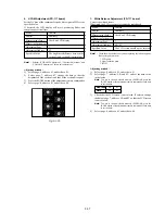
9. White Balance Check
Subject
Clear chart
(Color reproduction adjustment frame)
Filter
Filter C14 for color temperature
correction
ND filter 1.0 and 0.4 and 0.1
Measurement Point
Video output terminal
Measuring Instrument
Vectorscope
Specified Value
Fig. 5-1-12. A to C
Switch setting:
1)
NIGHT SHOT .................................................................. OFF
2)
DIGITAL ZOOM (Menu display) ................................... OFF
3)
STEADY SHOT (Menu display) ..................................... OFF
4)
VIDEO LIGHT ................................................................ OFF
Checking method:
1)
Check that the lens is not covered with either filter.
2)
Select page: 6, address: 01, set data: 0F, and press the PAUSE
button of the adjustment remote commander.
3)
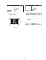
Check that the center of the white luminance point is within
the circle shown Fig. 5-1-12. (A).
4)
Select page: 6, address: 01, set data: 00, and press the PAUSE
button.
5)
Select page: 6, address: 01, set data: 23, and press the PAUSE
button.
6)
Place the C14 filter on the lens.
7)
Check that the center of the white luminance point settles in
the circle shown Fig. 5-1-12. (B).
8)
Remove the C14 filter, and place the ND filter 1.5 (1.0 +0.4+0.1)
on the lens.
9)
Check that the white luminance point stopped moving, and then
remove the ND filter 1.5.
10) Check that the center of the white luminance point settles within
the circle shown Fig. 5-1-12. (C).
Processing after Completing Adjustments
1)
Select page: 6, address: 01, set data: 00, and press the PAUSE
button of the adjustment remote commander.
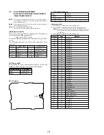
10. Steady Shot Check
(CCD-TRV57/TRV57P/TRV67/TRV87/TRV87P)
Precautions on the Angular Velocity Sensor Replacement
There are two types of repair parts.
Type A
ENC03JA
Type B
ENC03JB
Replace the broken sensor with a same type sensor. If replace with
other type parts, the image will vibrate up and down or left and
right during hand-shake correction operations. After replacing, check
the steady shot operations.
Precautions on Angular Velocity Sensor
The sensor incorporates a precision oscillator. Handle it with care
as if it dropped, the balance of the oscillator will be disrupted and
operations will not be performed properly.
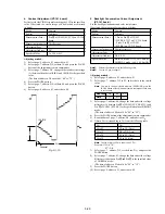
Steady Shot Check
Check the output of the angular velocity sensor.
Subject
Arbitrary
Measurement Point
Display data of page 1 (Note)
Measuring Instrument
Adjustment remote commander
Specified Value
PITCH data : 3100 to 4700
YAW data : 3100 to 4700
Note:
Displayed data of page 1 of the adjustment remote commander.
1 : XX : XX
Display data
Switch setting:
1)
ZOOM .................................................................... TELE end
2)
STEADY SHOT (Menu display) ...................................... ON
Checking method:
1)
Select page: 0, address: 03, and set data: 11.
2)
Select page: 1, and check that the PITCH data satisfies the
specified value.
3)
Select page: 0, address: 03, and set data: 12.
4)
Select page: 1, and check that the YAW data satisfies the
specified value.
Processing after Completing Adjustments
1)
Select page: 0, address: 03, and set data: 00.
2)
Check that the steady shot operations have been performed
normally.
R-Y
2mm
B-Y
2mm
R-Y
B-Y
1.5mm
3mm
3mm
R-Y
B-Y
3mm
3mm
3.5mm
1.0mm
Fig. 5-1-12. (A)
Fig. 5-1-12. (B)
Fig. 5-1-12. (C)
Содержание CCD-TRV67 - Video Camera Recorder 8mm
Страница 12: ...1 2 ...
Страница 13: ...1 3 ...
Страница 14: ...1 4 ...
Страница 15: ...1 5 ...
Страница 16: ...1 6 ...
Страница 17: ...1 7 ...
Страница 18: ...1 8 ...
Страница 19: ...1 9 ...
Страница 20: ...1 10 ...
Страница 21: ...1 11 ...
Страница 22: ...1 12 ...
Страница 23: ...1 13 ...
Страница 24: ...1 14 ...
Страница 25: ...1 15 ...
Страница 26: ...1 16 ...
Страница 27: ...1 17 ...
Страница 28: ...1 18 ...
Страница 29: ...1 19 ...
Страница 30: ...1 20E ...
Страница 82: ...CCD TR317 TR517 TRV17 TRV37 TRV47 TRV57 TRV57P TRV67 TRV87 TRV87P 4 41 4 42 USER CONTROL CF 66 ...
Страница 84: ...CCD TR317 TR517 TRV17 TRV37 TRV47 TRV57 TRV57P TRV67 TRV87 TRV87P 4 45 4 46 USER CONTROL CF 67 ...