


5-43
3-2.
SYSTEM CONTROL SYSTEM ADJUSTMENT
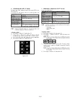
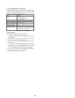
1. Initialization of D, E, F, 7 Page Data
If the D, E, F, 7 page data is erased due to some reason, perform “1-
2. INITIALIZATION OF D, E, F, 7 PAGE DATA”, of “5-1.
CAMERA SECTION ADJUSTMENT”
3-3.
SERVO SYSTEM ADJUSTMENTS
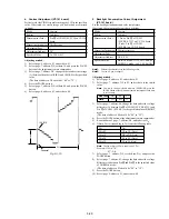
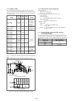
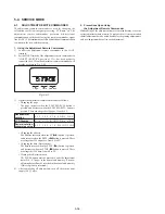
1. CAP FG Offset Adjustment (VC-234 board)
Improve the capstan servo characteristic. If it is not correct. jitters
will increase.
Mode
Camera recording (SP mode)
Subject
Arbitrary
Measurement Point
Pin
qs
of CN982 (CAP FG)
Measuring Instrument
Oscilloscope
Adjustment Page
F
Adjustment Address
64
Specified value
Duty = 50 ± 1 %
Adjusting method:
1)
Set to the Camera recording mode (SP mode).
2)
Select page: 0, address: 01, and set data: 01.
3)
Select page: 6, address: 01, set data: 81, and press the PAUSE
button of the adjustment remote commander. (to start up
automatic CAP FG offset adjustment.)
4)
Select page: 6, address: 02, and check that the data is “01”.
5)
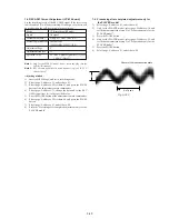
Check that Duty of CAP FG signal satisfies the specified value.
If not, select page: 6, address: 01, set data: 00, and press the
PAUSE button, and then, repeat steps 1) to 5).
6)
Select page: 6, address: 01, set data: 00, and press the PAUSE
button of the adjustment remote commander.
7)
Select page: 0, address: 01, and set data: 00.
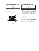
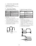
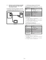
2. Switching Position Adjustment (VC-234 board)
If deviated in this case causes switching noise or jitter on the played
back screen.
Mode
Playback
Signal
Alignment tape:
For tracking adjustment
(WR5-1NP)
Measurement Point
CH1: Pin
qa
of CN982 (RF SWP)
CH2: Pin
6
of CN982 (PB RF)
Measuring Instrument
Oscilloscope
Adjustment Page
F
Adjustment Address
62, 63
Specified Value
t1 = 0 ± 10
µ
sec
Adjusting Method:
1)
Select page: 0, address: 01, and set data: 01.
2)
Select page: F, address: 22, set data: C0, and press the PAUSE
button of the adjustment remote commander.
3)
Select page: F, address: 62, change the data and minimize “t1”,
and then press the PAUSE button of the adjustment remote
commander. (Coarse adjustment)
4)
Select page: F, address: 63, change the data and adjust so that
the switching position (t1) becomes the specified value. (Fine
adjustment)
5)
Press the PAUSE button of the adjustment remote commander.
6)
Select page: F, address: 22, set data: 80, and press the PAUSE
button of the adjustment remote commander.
7)
Select page: 0, address: 01, and set data: 00.
A
B
Duty = A/B
×
100 [%]
Center of movement
CH1
CH2
Enlargement
t1=0
±
10
µ
sec
CH1
CH2
Fig. 5-3-4.
Fig. 5-3-5.
Содержание CCD-TRV67 - Video Camera Recorder 8mm
Страница 12: ...1 2 ...
Страница 13: ...1 3 ...
Страница 14: ...1 4 ...
Страница 15: ...1 5 ...
Страница 16: ...1 6 ...
Страница 17: ...1 7 ...
Страница 18: ...1 8 ...
Страница 19: ...1 9 ...
Страница 20: ...1 10 ...
Страница 21: ...1 11 ...
Страница 22: ...1 12 ...
Страница 23: ...1 13 ...
Страница 24: ...1 14 ...
Страница 25: ...1 15 ...
Страница 26: ...1 16 ...
Страница 27: ...1 17 ...
Страница 28: ...1 18 ...
Страница 29: ...1 19 ...
Страница 30: ...1 20E ...
Страница 82: ...CCD TR317 TR517 TRV17 TRV37 TRV47 TRV57 TRV57P TRV67 TRV87 TRV87P 4 41 4 42 USER CONTROL CF 66 ...
Страница 84: ...CCD TR317 TR517 TRV17 TRV37 TRV47 TRV57 TRV57P TRV67 TRV87 TRV87P 4 45 4 46 USER CONTROL CF 67 ...