


5-20
2. Flange Back Adjustment
(Using Minipattern Box)
The inner focus lens flange back adjustment is carried out
automatically. In whichever case, the focus will be deviated during
auto focusing/manual focusing.
Subject
Siemens star chart with ND filter for
the minipattern box (Note1)
Measurement Point
Check operation on TV monitor
Measuring Instrument
Adjustment Page
F
Adjustment Address
4E to 5D
Note1:
Dark Siemens star chart.
Note2:
Make the lens horizontal and perform this adjustment.
Switch setting:
1)
NIGHT SHOT .................................................................. OFF
2)
DIGITAL ZOOM (Menu display) ................................... OFF
3)
STEADY SHOT (Menu display) ..................................... OFF
4)
VIDEO LIGHT ................................................................ OFF
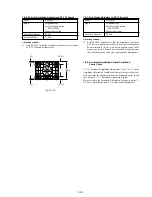
Preparations before adjustments:
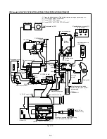
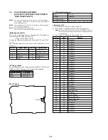
The minipattern box is installed as shown in the following figure.
Note:
The attachment lenses are not used.
Specified voltage:
The specified voltage varies according to the
minipattern box, so adjust the power supply
output voltage to the specified voltage written
on the sheet which is supplied with the
minipattern box.
Adjusting method:
1)
Install the minipattern box so that the distance between it and
the front of the lens of the camcorder is less than 3cm.
2)
Make the height of the minipattern box and the camcorder equal.
3)
Check that the output voltage of the regulated power supply is
the specified voltage.
4)
Check that at both the zoom lens TELE end and WIDE end,
the center of the Siemens star chart and center of the exposure
screen coincide.
5)
Select page: 0, address: 01, and set data: 01.
6)
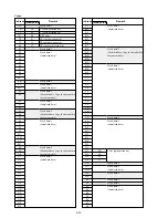
Check that the data of page: F, address: 4E to 5D is the initial
value (See table below).
7)
Select page: 6, address: 02, and check that the data is “00”.
8)
Select page: 6, address: 01, set data: 13, and press the PAUSE
button of the adjustment remote commander.
9)
Select page: 6, address: 01, set data: 27, and press the PAUSE
button.
(The adjustment data will be automatically input to page: F,
addresses: 4E to 5D.)
10) Select page: 6, address: 02, and check that the data is “01”.
Processing after Completing Adjustments:
1)
Select page: 0, address: 01, and set data: 00.
2)
Turn off the power and turn on again.
3)
Perform “Flange Back Check”.
Address
4E
4F
50
51
52
53
54
55
Data
28
07
3A
4A
12
0B
54
00
Address
56
57
58
59
5A
5B
5C
5D
Data
19
00
37
00
00
04
00
00
Minipattern box
Below 3 cm
Camcorder
Camera
table
Red (+)
Black (–)
Yellow (SENS +)
White (SENS –)
Black (GND)
Need not connected
Regulated power supply
Output voltage : Specified voltage
±
0.01Vdc
Output current : more than 3.5A
Fig. 5-1-7.
Содержание CCD-TRV67 - Video Camera Recorder 8mm
Страница 12: ...1 2 ...
Страница 13: ...1 3 ...
Страница 14: ...1 4 ...
Страница 15: ...1 5 ...
Страница 16: ...1 6 ...
Страница 17: ...1 7 ...
Страница 18: ...1 8 ...
Страница 19: ...1 9 ...
Страница 20: ...1 10 ...
Страница 21: ...1 11 ...
Страница 22: ...1 12 ...
Страница 23: ...1 13 ...
Страница 24: ...1 14 ...
Страница 25: ...1 15 ...
Страница 26: ...1 16 ...
Страница 27: ...1 17 ...
Страница 28: ...1 18 ...
Страница 29: ...1 19 ...
Страница 30: ...1 20E ...
Страница 82: ...CCD TR317 TR517 TRV17 TRV37 TRV47 TRV57 TRV57P TRV67 TRV87 TRV87P 4 41 4 42 USER CONTROL CF 66 ...
Страница 84: ...CCD TR317 TR517 TRV17 TRV37 TRV47 TRV57 TRV57P TRV67 TRV87 TRV87P 4 45 4 46 USER CONTROL CF 67 ...


