


5-40
3-1-2. Precautions on Adjusting
Note1:
TR model / TRV model
TR model: CCD-TR317/TR517
TRV model: CCD-TRV17/TRV37/TRV47/TRV57/TRV57P/
TRV67/TRV87/TRV87P
1)
The adjustments of this unit are performed in the VTR mode
or camera mode.
To set to the VTR mode, set the power switch to “VTR or
PLAYER” or set the “Forced VTR Power ON mode” using the
adjustment remote commander (Note 2).
To set to the Camera mode, set the power switch to “CAMERA”
or set the “Forced Camera Power ON mode” using the
adjustment remote commander (Note 3).
After completing adjustments, be sure to exit the “Forced VTR
Power ON Mode” or “Forced Camera Power ON Mode”. (Note 4)
2)
By setting the “Forced VTR Power ON mode” or “Forced
Camera Power ON mode”, the video section can be operate
even if the front panel block (MA-374/375 board, power switch,
microphone unit) has been removed. When removing the front
panel block, disconnect the following connector.
1. VC-234 board CN972 (20P 0.5mm)
3)
The cabinet (R) (Camera function switch (CF-66/67 board),
LCD block (TRV model only), Viewfinder) need not be
connected. But removing the cabinet (R) (removing the VC-
234 board CN975) means removing the lithium 3V power
supply (CF-66/67 board BH001), data such as date, time, user-
set menus will be lost. After completing adjustments, reset these
data. If the cabinet (R) has been removed, the self-diagnosis
data, data on history of use (total drum rotation time etc.) will
be lost. Before removing, note down the self-diagnosis data
and data on history use (data of page: 2, address: A2 to AA).
(Refer to the “Service Mode” for the data on the history use.)
To remove the cabinet (R), disconnect the following connectors.
1. VC-234 board CN975 (45P, 0.5mm)
2. DD-134 board CN933 (8P, 1.0mm)(TRV model only)
4)
The video light board (VL-29 board) need not be connected.
To remove, disconnect the following connector. (Except for
CCD-TR317/TR517/TRV47)
1. VL-29 board CN151 (8P, 0.5mm)
5)
The lens block (CD-239/240 board) need not be connected. To
remove, disconnect the following connectors.
1. VC-234 board CN501 (14P, 0.5mm)
2. VC-234 board CN551 (24P, 0.5mm)
Note2:
Setting the “Forced VTR Power ON” mode (VTR mode)
1) Select page: 0, address: 01, and set data: 01.
2) Select page: D, address: 10, set data: 02, and press the PAUSE
button of the adjustment remote commander.
The above procedure will enable the VTR power to be turned
on with the front panel block removed.
After completing adjustments, be sure to exit the “Forced VTR
Power ON mode”.
Note3:
Setting the “Forced Camera Power ON” mode (Camera mode)
1) Select page: 0, address: 01, and set data: 01.
2) Select page: D, address: 10, set data: 01, and press the PAUSE
button of the adjustment remote commander.
The above procedure will enable the camera power to be turned
on with the front panel block removed.
After completing adjustments, be sure to exit the “Forced
Camera Power ON mode”.
Note4:
Exiting the “Forced Power ON” mode
1) Select page: 0, address: 01, and set data: 01.
2) Select page: D, address: 10, set data: 00, and press the PAUSE
button of the adjustment remote commander.
3) Select page: 0, address: 01, and set data: 00.
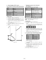
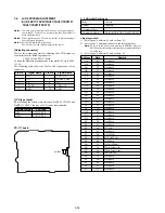
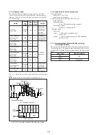
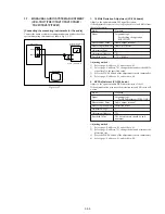
3-1-3. Adjusting Connectors
Some of the adjusting points of the video section are concentrated
at VC-234 board CN982. Connect the measuring instruments via
the CPC-7 jig (J-6082-382-A). The following table lists the pin
numbers and signal names of CN982.
Table 5-3-1.
Pin No.
1
2
3
4
5
6
7
8
Signal Name
LANC SIG
XCPC IN
IR VIDEO
AFC F0
BPF MONI
PB RF
RF AGC IN
REG GND
Pin No.
9
10
11
12
13
14
15
16
Signal Name
RF AGC OUT
REC RF
RF SWP
CAP FG
EVF BL
EVF BL 4.75V
VCO
EVF VG
CN982
1
16
Screw driver (–)
CPC lid (BT)
Fig. 5-3-1.
Содержание CCD-TRV67 - Video Camera Recorder 8mm
Страница 12: ...1 2 ...
Страница 13: ...1 3 ...
Страница 14: ...1 4 ...
Страница 15: ...1 5 ...
Страница 16: ...1 6 ...
Страница 17: ...1 7 ...
Страница 18: ...1 8 ...
Страница 19: ...1 9 ...
Страница 20: ...1 10 ...
Страница 21: ...1 11 ...
Страница 22: ...1 12 ...
Страница 23: ...1 13 ...
Страница 24: ...1 14 ...
Страница 25: ...1 15 ...
Страница 26: ...1 16 ...
Страница 27: ...1 17 ...
Страница 28: ...1 18 ...
Страница 29: ...1 19 ...
Страница 30: ...1 20E ...
Страница 82: ...CCD TR317 TR517 TRV17 TRV37 TRV47 TRV57 TRV57P TRV67 TRV87 TRV87P 4 41 4 42 USER CONTROL CF 66 ...
Страница 84: ...CCD TR317 TR517 TRV17 TRV37 TRV47 TRV57 TRV57P TRV67 TRV87 TRV87P 4 45 4 46 USER CONTROL CF 67 ...


