background image

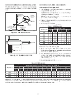
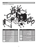
The ComfortSense

®

 7000/7500 Thermostat, the iComfort 

Wi-Fi

®

 Thermostat, or the iComfort

®

 S30 Thermostat (when 

using an iComfort

®

 enabled HVAC system) can be used as 

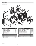
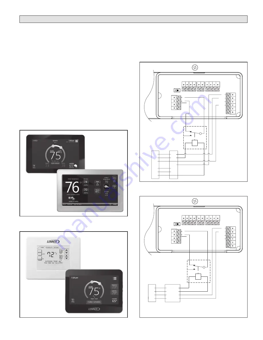
an external control, if used with a relay. The recommended 

relay is Catalog # 69J79. See 

Figures 18 & 19

 for wiring. 

The NC NO slide switch should remain in the NO position. 
When an external control is enabled, “EXTERNAL” will be 

displayed on the dehumidifier control. External controls are 

recommended when the dehumidifier is installed in an attic 

and is ducted to the HVAC system. 
If an external control is used in a zoned application, it must 

be located in the Primary Zone (refer to TWO ZONE – 

PRIMARY AND SECONDARY zoned installation on page 

15 for details). 

NOTE: When using an external control, there is a 3 

minute delay at start-up or whenever power is cycled 

to the dehumidifier. As with any configuration, the 

compressor has a 3 minute minimum on and off time.

NOTE:

 Both the ComfortSense

®

 7000/7500 Thermostat 

and the iComfort

®

 Thermostats use reverse logic for 

dehumidification. There is 24VAC between the DH and 

C terminals when there is no call for dehumidification. 

Figures 18 & 19

 show relay position when there is a call for 

dehumidification and 0VAC between the DH and C terminals.

Figure 18. ComfortSense

®

 7000/7500 Thermostat Wiring

Figure 19. iComfort

®

 Thermostat Wiring

Figure 17. ComfortSense

®

 Touchscreen Thermostats

Figure 16. iComfort

®

 Thermostats

+ - A B ODT

FLOA

T

Switch

DH

DH

Gh
Rf
Cf

Gs

Y

W

HV

AC EQUIP

.

HVAC

Unit

NC NO

NC

NO

ComfortSense

®

7000/7500

Thermostat

SPDT RELAY

R
C

G

Y

W

R
C
G

DH

Y

W

+ - A B ODT

FLOA

T

Switch

DH

DH

Gh
Rf
Cf

Gs

Y

W

HV

AC EQUIP

.

DH

C

G

R

R
I+
I-
C

iComfort

Enabled

HVAC Unit

NC NO

NC

NO

R
I+
I-
C

iComfort

Thermostat

SPDT RELAY

90-1989

90-1979

Lennox Control

iComfort

®

 S30 

Thermostat 

(Catalog # 12U67)

ComfortSense

®


7000 Touchscreen 

Thermostat 

(Catalog # Y2081)

iComfort Wi-Fi

®


Thermostat 

(Catalog # 10F81)

ComfortSense

®


7500 Touchscreen 

Thermostat 

(Catalog # 13H14)

9

Содержание HCWHD3-070

Страница 1: ...er Table of Contents Safety Instructions 1 Specifications 2 Packaging Content 2 Set Up Dehumidifier for Installation 3 Duct Collars 3 Control Location 4 Hard Wire Modification 4 Electrical Specificati...

Страница 2: ...dew point minimum Ventilation 40 F 140 F 0 RH 99 RH non condensing Filter MERV 8 washable Airflow External Static Pressure w c Airflow CFM External Static Pressure w c Airflow CFM External Static Pre...

Страница 3: ...not being used See Figure 2 Make sure there are no bends in the duct coming off the outlet for a minimum of 4 This will ensure that the duct will not interfere with the backflow damper function Figur...

Страница 4: ...ower supply at the 115VAC terminals on the dehumidifier United States Installations Make all electrical connections in accordance with the current edition of the NEC ANSI NFPA 70 and any local codes o...

Страница 5: ...lectrical service at the main fuse or circuit breaker box SIDE PANEL ELECTRICAL SERVICE BOX POWER CORD STRAIN RELIEF 90 1900 Figure 5 Electrical Service Box Location Location Considerations Allow suff...

Страница 6: ...te pump is needed install it in the condensate pan as well Install a condensate overflow safety switch i e float switch in the condensate pan remove the factory installed jumper wire between the Float...

Страница 7: ...illes with 10 Duct Collars Ducting Notes Use insulated duct when the dehumidifier is located in an unconditioned space such as an attic or a garage Use a minimum of 12 of flex duct at the dehumidifier...

Страница 8: ...dehumidification needs of the Primary Zone have been satisfied NOTE Dehumidifier controls will not work with iHarmony Zoning Systems IMPORTANT Normally Closed dampers must be installed in the ducts se...

Страница 9: ...he compressor has a 3 minute minimum on and off time NOTE Both the ComfortSense 7000 7500 Thermostat and the iComfort Thermostats use reverse logic for dehumidification There is 24VAC between the DH a...

Страница 10: ...used If an external control is used in a zoned application it must be located in the Primary Zone refer to TWO ZONE PRIMARY AND SECONDARY zoned installation on page 15 for details NOTE When using an e...

Страница 11: ...wired to the HVAC system to prevent short circuiting dehumidified air directly back to the dehumidifier inlet In return to supply ducting configuration running the HVAC fan with the dehumidifier ensu...

Страница 12: ...o to the ZONE screen selections System Set up and Checkout If dehumidifier installation does not include ventilation or zoning and will not be wired to an external control remote control or the HVAC s...

Страница 13: ...select DISABLED and press MODE to go to the EXTERNAL control screen selections 90 1854 If installing the dehumidifier in a two zone application use the UP or DOWN arrows to select ENABLED and press MO...

Страница 14: ...TEST will show on the display If wired to the HVAC system the HVAC blower will turn on and if there is are damper s wired to the DEH DAMPER terminals of the control the damper s will energize 90 1854...

Страница 15: ...alling for dehumidification The dehumidifier and HVAC blower if on will turn off when the RH measured by the Y6456 drops 3 RH below the setting CRAWL SPACE OR SEALED ATTIC REMOTE CONTROL USING Y6456 1...

Страница 16: ...lation is only allowed during a HVAC heat call Vent Auto C Ventilation prevented when outdoor temperature is below 0 F and above 100 F Vent Auto D Ventilation prevented when outdoor temperature is bel...

Страница 17: ...resh Air Delivery Rate 1 Measure the negative static pressure of the return system at the location where the fresh air intake duct enters the return duct or dehumidifier inlet 2 See Table 2 for estima...

Страница 18: ...NSTALLER SETTINGS 90 1854 With the dehumidifier power switch on press the ON OFF button to turn the dehumidifier off 90 1854 Press and hold the MODE button for 3 seconds to access the installer settin...

Страница 19: ...the dehumidifier compressor will turn on to remove moisture Ventilation with an External Control When an external control is installed the dehumidifier will open the ventilation damper only when ther...

Страница 20: ...SAMPLING and ON the humidity measured by the internal sensor while also displaying RH and ON and the frost sensor temperature while also displaying ON Scroll through these values and by using the UP D...

Страница 21: ...LER TEST mode Incorrect damper wiring or bad connection Verify wiring between dampers and 24 VAC transformer If wired for Two Zone operation verify that 24 VAC transformer is 40 VA minimum Check all w...

Страница 22: ...SENSOR LOW TEMP SENSOR HI TEMP JUMPER ORG BLUE 24 VAC CMP_N CMP_L FAN_N FAN_L NTRL_F NTRL_C LINE_F LINE_C C S R ORG RED BRN BRN BLK BLK BRN BLU GRN YEL GRN BLK BLK WHT WHT BLK WHT N L WHT BLU RED YEL...

Страница 23: ...Deh Y6467 Fan 95pt Deh Y6468 No Part Description Part No 12 Wire Harness Power Deh Y6469 13 Sensor Low Temperature Deh Y6470 14 Sensor High Temperature Deh Y6471 15 Leveling Foot Deh Y6472 16 Capacito...

Страница 24: ...1 6 Door Filter Access Deh Y7121 7 Outlet Duct Panel Deh Y6463 8 Backflow Damper 10 Deh Y6464 9 Inlet Duct Panel Deh Y6465 10 Cover Outlet Deh Y6466 No Part Description Part No 11 Fan 130pt Deh with 1...

Отзывы: