


Control Faults
Control faults will typically result in either the corruption of display information, or the failure of encoders and switches. The
{ |>=* ;[`
section meter panel. The CPU uses several serial data busses to carry control data, such as fader position data and switch presses,
to the CPU as well as display data, such as LED illumination commands, to the displays and motor drive information to the faders.
Referring to the Matrix Control Block Schematic you will see that there are four Digital Data bus connections to the CPU:
\ G { |>| |
the routing matrix.
The second, labeled ‘Tile-control’, daisy chains through the 629506X1 into the 626507X1, back into the 629506X1 and the
through the two 629502XA solo and cut panels. This data chain carries switch presses and rotary encoder data to the CPU and
&< ;[`" \G
which is converted from analogue to digital position data on the 629502XA assemblies.
The third connection, labeled ‘Channels’, connects the 629515X1 and 629511X1 assemblies to the CPU using a ‘Y’ split cable and
then daisy chains through the 629511X1 to the two 629510X1 assemblies. This third connection also carries switch press data
from the analogue modules and LED data from the CPU. This connection also carries a separate MDAC (Multiplying Digital to
Analogue Converter) control bus which writes gain data to the channel and centre section MDAC elements.
Finally the forth connection, labeled ‘meters’, daisy chains through the three meter assemblies driving the LED bar graph displays.
" { #
of data will be interrupted and assemblies after that point in the chain will fail to function.
The following example highlights a data bus fault and explains how the fault might be located.
After powering on the console you notice that the data displays for channels 1 to 8 are blank and the corresponding solo and
cut switches work but do not illuminate.
Once again refer to the Matrix Control Block Schematic. From the diagram you can see that data bus for the left 629502XA
assembly is connected to socket labeled ‘out’ on the right 629502XA assembly and the power is supplied from the left hand
629516X1 routing assembly. From the fault description we know that the data from the switches is reaching the CPU so the
power to the assembly must be good so we can rule this out.
We know that the display data is reaching the right hand 629502XA assembly as the displays and LEDs are functioning correctly.
From this we can conclude that the problem must be with either the output of the right assembly or the input of the left
|>=*>"\# \
not seated correctly. The second is that the input stage to left hand 629502Xa assembly is faulty. The third is that the right hand
panel has a faulty output stage.
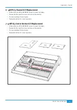
\ [;_ |>=*>"]
Replacing Modules information at the end of this section). Remove and then reinsert the 34 way ribbon connector between the
two 629502XA assemblies to ensure that a sound connection is made. Re-assemble the console and check the condition of the
fault. For the sake of the example we will assume that this did not resolve the problem.
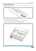
The next possibility to eliminate is that one of the 629502XA Panels is faulty. Power down the console and swap the two
assemblies. Re-power the console. If the panel originally in the left hand position was faulty, then neither panel will now function.
@ # @#
{ "
hand panel is not required to buffer data onto another panel, this fault will not effect the operation of the console and can be left
in this position allowing you to continue working unhindered.
Appendix G - Service
143
Matrix
2
Owner’s Manual
Содержание Matrix2 Delta
Страница 37: ... Chapter 2 Getting Started 29 Matrix2 Owner s Manual ...
Страница 128: ... Chapter 6 DAW and CC Configuration 120 Matrix2 Owner s Manual ...
Страница 136: ...Appendix B Technical Specifications 128 Matrix2 Owner s Manual ...
Страница 140: ... Appendix D Environmental Specifications 132 Matrix2 Owner s Manual ...
Страница 142: ... Appendix E Software Updates 134 Matrix2 Owner s Manual ...
Страница 178: ... Appendix G Service 170 Matrix2 Owner s Manual ...
Страница 179: ......