background image

6

  |  important Safety Precautions

iMPOrTAnT SAFETY PrECAUTiOnS

SAVE THESE INSTRUCTIONS

This manual contains important safety instructions. read all safety and operating instructions before operating the 

Uninterruptible Power System (UPS). Adhere to all warnings on the unit and in this manual. Follow all operating and user 

instructions. This equipment can be operated by individuals without previous training.
This product is designed for data processing equipment; commercial/industrial use only. it is not intended for use with 

life support or other designated “critical” devices. Maximum load must not exceed that shown on the UPS rating label. if 

uncertain about the application, consult your dealer or local SolaHD representative.
This UPS is designed for use on a properly grounded (earthed) 220–240 V ac; 50 or 60 Hz supply. installation must be 

performed by qualified personnel.  A qualified electrician must review and approve customer supplied wiring, circuit 

breakers, intended loads and verify correct input, output, and earth connections to ensure compliance with technical 

standards and local codes of practice. installation instructions and “for use by qualified personnel only” warning notices 

are in this manual.

!

 wARNINg

Although the UPS has been designed and manufactured to ensure personal safety, improper use can result in elec-

trical shock or fire. To ensure safety, observe the following precautions:

• 

Turn off and unplug the UPS before cleaning it.

• 

Clean the UPS with a soft, dry cloth. Do not use liquid or aerosol cleaners.

• 

Never block or insert any objects into the ventilation holes or other openings of the UPS.

• 

Do not place the UPS power cord where it might be damaged.

Operate the UPS in an indoor environment only, in an ambient temperature range of 0°C to +40°C (+32°F to +104°F). 
install the UPS in a clean environment, free from moisture, flammable liquids, gases, and corrosive substances.
This UPS contains no user-serviceable parts except the internal battery pack. The UPS On/Off buttons do not electrically 

isolate internal parts. Under no circumstances should you attempt to gain access internally due to the risk of electric 

shock or burn.
Do not continue to use the UPS if the front panel indicators are not in accordance with these operating instructions or the 

UPS performance alters in use. refer all faults to your SolaHD representative.
DO nOT COnnECT equipment that could overload the UPS or demand dc current from the UPS, for example: electric 

drills, vacuum cleaners, laser printers, hair dryers, or any appliance using half-wave rectification.
Storing magnetic media on top of the UPS may result in data loss or corruption.

NOTICE:

 if this UPS is supplied from an “iT” electrical power system, the jumper on the rear panel must be disconnected. 

See “8.8 iT Power System Configuration” for details. When connecting to an “iT” system, the installer must provide a 2-pole 

upstream circuit breaker. refer to all local and national codes when installing the upstream breaker.

Содержание S4K5U6K5C

Страница 1: ...S4KC Series Industrial On line UPS 230 V 6000 VA User Manual...

Страница 2: ...liability for damages resulting from use of this information or for any errors or omissions The SolaHD and Emerson logos are registered in the U S Patent and Trademark Office All other product or ser...

Страница 3: ...0 System Description 10 2 1 Surge Protection Devices EMI RFI Filters 10 2 2 Rectifier Power Factor Correction Circuit 10 2 3 Inverter 10 2 4 Battery Charger 11 2 5 Dc to Dc Converter 11 2 6 Battery 11...

Страница 4: ...Configuration Program 25 6 1 Configuration Program Features 25 6 1 1 What You Will Need 25 7 0 Controls Indicators 26 7 1 On Alarm Silence Manual Battery Test Button 26 7 2 Standby Manual Bypass Butto...

Страница 5: ...Power Off 34 10 0 Maintenance 35 10 1 Replacing the Internal Battery Pack 35 10 1 1 Battery Replacement Procedures 35 10 2 Battery Charging 36 10 4 Checking UPS Status 37 10 5 Checking UPS Functions...

Страница 6: ...wing precautions Turn off and unplug the UPS before cleaning it Clean the UPS with a soft dry cloth Do not use liquid or aerosol cleaners Never block or insert any objects into the ventilation holes o...

Страница 7: ...eir own expense The S4K5U6K5C complies with the requirements of EMC Directive 2004 108 EC and the published technical standards Continued compliance requires installation in accordance with these inst...

Страница 8: ...followed by important instructions Ac input Ac output Requests the user to consult the manual Indicates the unit contains a valve regulated lead acid battery Recycle Dc voltage Equipment grounding co...

Страница 9: ...sine wave power The S4K5U6K5C features a light emitting diode LED display to indicate both load percentage and battery capacity It also provides self diagnostic tests a combination ON Alarm Silence Ma...

Страница 10: ...ac power to regulated dc power for use by the inverter while ensuring that the wave shape of the input current used by the UPS is near ideal Extracting this sine wave input current achieves two object...

Страница 11: ...e UPS in an ambient temperature of 15 C to 25 C 59 F to 77 F Optional external battery cabinets are available to extend battery backup times For backup times see Table 12 2 7 Dynamic Bypass The UPS pr...

Страница 12: ...wer Bezel and Battery Access Door Upper Bezel Figure 2 Front view rack mount and tower configurations External Battery Connector IT Power System Access Cover C13 Output Receptacles C19 Output Power Re...

Страница 13: ...4 Internal battery pack features 3 3 Removable Power Distribution Box The UPS is shipped with a power distribution box installed This box contains the UPS input circuit breaker NOTE Hardwire and hard...

Страница 14: ...sentative immediately 4 2 What s Included The S4K5U6K5C is shipped with the following items Compact disk with MultiLink Configuration program and User manual electronic version One USB cable 2 m 6 1 2...

Страница 15: ...uces ventilation and heat dissipation shortening the service life of the unit Maintain an ambient temperature range of 0 C to 40 C 32 F to 104 F NOTE UPS operation in sustained temperatures outside th...

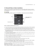
Страница 16: ...e front metal bezel cover b Using the finger grips on the display panel gently pull and rotate 90 degrees clockwise and snap it back into position as shown in Figure 8 Figure 8 Rotate the operation an...

Страница 17: ...3 mm 18 32 in deep The weight limit per pair of adjustable rack mounting brackets is 91 kg 200 lb Parts included Two rear bracket members two front bracket members two inner bracket members Sixteen M4...

Страница 18: ...me mounting height on all four rack mounting rails M5 screws M5 screws Front rack mounting rails Figure 10 Installing the rear member and front member of each bracket assembly 4 Get eight M4 screws an...

Страница 19: ...et Figure 12 Fastening the inner members 6 If available apply a bead of grease 25 mm 1 in long at four places inside the bottom curved tracks of the front members as shown in Figure 13 The grease will...

Страница 20: ...ket assemblies If it does not recheck the alignment of the front and rear members from Steps 2 and 3 Insert the UPS into the front members Lift the front and push it into the rack Figure 14 Insert the...

Страница 21: ...de rail kit 4 Use the enclosed support bases for the tower option to prevent tip over One additional set of support base extensions ships with each external battery cabinet 5 Put the UPS into Bypass M...

Страница 22: ...pass 4 Turn the output and input breakers off 5 Loosen other captive screws until the power distribution box releases 6 Remove the power distribution box from the UPS and set it aside 7 Loosen the scr...

Страница 23: ...s Model Maximum Breaker Rating S4K5U6K5C D Type 32 A This UPS is equipped with a manual bypass breaker It passes bypass power directly to the bypass breaker from the input terminal block The input cir...

Страница 24: ...mm2 8 AWG 2 26 N m 20 in lb NOTES The installer must provide circuit breaker protection according to local codes The mains disconnect should be within sight of the UPS or have an appropriate lock out...

Страница 25: ...ch local voltages Enable Disable Auto Restart Select frequency converter operation with a fixed output frequency of 50 or 60 Hz Set the Low Battery alarm time to a value of 2 to 30 minutes Enable Disa...

Страница 26: ...battery test press the On button for at least one second while operating from mains power with no alarm conditions present If only three of the five Battery LEDs illuminate allow the UPS to recharge...

Страница 27: ...increments 5 The Battery Level indicators will illuminate as shown in Figure 21 The Battery Level indicators display approximate battery capacity at all times The UPS is equipped with automatic and re...

Страница 28: ...ult Ac Input indicator Green On when the mains input power is normal off during mains failure flashing when mains power is outside the specifications Battery indicator Amber On when the battery is sup...

Страница 29: ...re used verify that the battery cables are fully inserted in the sockets 5 Place the manual bypass breaker in the BYPASS position 6 Turn on the branch circuit disconnect to apply voltage to the input...

Страница 30: ...hut Down the UPS 1 Transfer the UPS to manual bypass by pressing the Standby Manual Bypass button once hold it for about 2 seconds If manual bypass is not available disregard the first step 2 Press th...

Страница 31: ...the connectors as shown in Figure 22 3 Reinstall IT power system access cover and screws NOTE When connecting to an IT system the installer must provide a 2 pole upstream circuit breaker Refer to all...

Страница 32: ...history log Any Mode Shutdown can be operated locally or remotely Local Any Mode Shutdown can be performed by shorting the Pins in Set 3 Remote Any Mode Shutdown can be performed using a switch connec...

Страница 33: ...ctor Battery Mode Shutdown wiring must conform to all national regional and local wiring codes and laws This signal must last for 1 5 seconds or longer A Battery Shutdown signal will not cause an imme...

Страница 34: ...can be configured to coordinate shutdown across the network with other computers running MultiLink when you purchase a MultiLink License Kit For more information about the IntelliSlot SNMPWEB Card and...

Страница 35: ...appropriate replacement battery pack 10 1 1 Battery Replacement Procedures 1 Gently remove the front metal bezel cover from the UPS 2 Loosen and remove the six screws on the battery door as shown in F...

Страница 36: ...ttery packs 9 Reconnect the battery plugs and battery receptacles 10 Gently push the battery wire into the UPS battery compartment 11 Reattach the front battery door with the six screws 12 Reattach th...

Страница 37: ...act your local SolaHD representative or SolaHD Technical Support Check whether the battery is discharging When the mains input is normal the battery should not discharge If the UPS is operating in Bat...

Страница 38: ...icator Descriptions Indicator Diagnosis Audible Alarm A E On bypass from output overload Half second beep every half second A On bypass due to overtemperature condition 1 second beep every 4 seconds B...

Страница 39: ...iptions Condition Alarm Battery discharge Half second beep every 10 seconds Low battery Two half second beeps every 5 seconds UPS fault load on bypass 1 second beep every 4 seconds UPS fault no power...

Страница 40: ...is within acceptable limits for the UPS UPS has reduced battery backup time Batteries are not fully charged Keep the UPS plugged in continuously for at least 24 hours to recharge the batteries UPS is...

Страница 41: ...Support Fault indicator and Diagnostic A and B indicators are illuminated continuous alarm sounds UPS failure includes dual fan failure single fan failure under certain condi tions and battery charge...

Страница 42: ...e Power Distribution Box output ac parameters Factory Default V ac 230 V ac Output Connections S4KPAD2 CEHWMBSC Standard See 3 3 Removable Power Distribution Box Frequency 50 or 60 Hz nominal Wave for...

Страница 43: ...Transportation ISTA Procedure 1A Table 8 Operating Temperature Parameters Ambient Temperature Model Number S4K5U6K5C pf 30 C 3 C pf 86 F 5 4 F 0 8 pf pf 40 C 3 C pf 104 F 5 4 F 0 8 pf Table 9 Power Di...

Страница 44: ...ated non spillable lead acid Qty x V x Rating 20 x 12 V x 9 0 Ah Battery Mfr Part Number Yuasa REW 45 12 Backup Time See Table 12 Recharge Time 3 hours to 90 capacity after full discharge into 100 loa...

Страница 45: ...Unit 43 0 94 8 Shipping 54 0 119 0 Battery parameters Type Valve regulated non spillable lead acid Qty x V 1 x 20 x 12 V Battery Mfr Part Number Yuasa NPH5 12 Backup Time See Table 12 environmental r...

Страница 46: ...backup times at different loads 12 1 Auto learning Battery Backup Times As batteries age the estimated backup times may become less accurate The S4K5U6K5C is programmed to learn from a full battery di...

Страница 47: ...Warranty 13 1 Product Registration To register your product for updates and information on service and support visit our Web site at http www solahd com support registration htm 13 2 Warranty Informa...

Страница 48: ...SolaHD U S 800 377 4384 International 847 268 6000 www solahd com P N A272 226 Rev 1 08 16 10...

Отзывы: