S4KC SEriES USEr MAnUAL |
21
5.3 External Battery Cabinet Installation
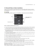
Optional external battery cabinets may be connected to the UPS to provide additional battery backup times. External
battery cabinets are designed to be placed on one side of the UPS in a tower configuration or stacked beneath the UPS in
a rack configuration.
!
CAUTION
The external battery cabinet(s) are heavy (see “12.0 Specifications). Take proper precautions when lifting them.
Cables connecting battery
cabinets to UPS
UPS
Battery cabinets
Figure 15: Typical external battery cabinet connections
1.
inspect the external battery cabinet for freight damage. report damage to the carrier and your SolaHD representative.
2.
For slide rail installations, first remove the top/side fin. Top/side fin slides forward and then lift up to remove. Optional
rack-mount handles are shipped with the external battery cabinet and may be installed at this time if desired.
3.
Securing hardware and slide rails are sold separately. Please contact your local dealer or SolaHD representative for
these additional options and any assistance needed. Fasten the slides into position with the screws per the instructions
included with the slide rail kit.
4.
Use the enclosed support bases for the tower option to prevent tip-over. One additional set of support base extensions
ships with each external battery cabinet.
5.
Put the UPS into Bypass Mode by pressing the Standby/Manual Bypass button one time (hold it for about 2 seconds).
6.
Verify the external battery cabinet breaker is in the Off position.
7.
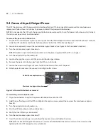
Connect the supplied external battery cabinet cable to the rear of the external battery cabinet, then to the rear of the UPS.
8.
Turn the external battery cabinet breaker to the On position.
9.
Press the On button on the front of the UPS for four seconds to return the unit to inverter Mode.
10.
Verify the circuit breaker on the external battery cabinet is in the On position.
11.
Use the included configuration program to program the UPS for the number of external battery cabinets connected.
instructions for the configuration program are in “6.0 Configuration Program”.
12.
The UPS is now equipped with additional battery backup time. refer to Table 12 for approximate backup times.
NOTE:
When removing the external battery cabinet, the circuit breaker on the rear of the cabinet must be turned off
before disconnecting the cable.
NOTE:
if the UPS is to be shipped or stored for an extended time, the connector should be disconnected. This will mini-
mize any standby current drain on the batteries and help attain their design life.


