14
PROCESS SELECTION (cont.)
M. (-)NEGATIVE TERMINAL
Negative output terminal. The
work cable is plugged into this
terminal during standard weld-
ing operation. The Power plug
can be inserted into this termi-
nal for straight polarity weld-
ing on very light sheet metal, or
for using flux cored gasless
wire.
WELDING
Optimum control settings will
vary according to the thickness of
the metal, the type of joint,
operator preference, etc. Best
results can be obtained through
experience with the welding machine
or by making trial welds. Select
some sample material of the same
type and thickness as the material
to be welded. Set the welding
controls(using the parameter chart
located on the door of the feed unit
or on page 25) for optimum results
using the sample material thickness
and wire size being used as a
starting point, weld until experi-
ence is gained using the unit.
CONTINUOUS WELDING ON
STEEL
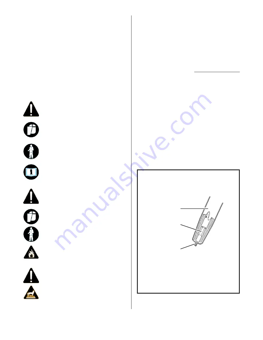
1. Trim the electrode wire to leave
approximately 1/4 inch stickout
beyond the end of the contact tip
and install the welding nozzle.
The contact tip should be flush
or stick out up to 1/16 inch
beyond the end of the nozzle.
FIG. 17. NOZZLE ADJUSTMENT
FOR WELDING STEEL
NOZZLE
CONTACT TIP
(FLUSH TO
1/16" STICKOUT)
ELECTRODE WIRE
(1/4" STICKOUT)
WARNING
• Materials can cause sparks or flying metal
when heated which can cause fire.
Wear safety shield and protective cloth-
ing (user and bystanders).
Sparks, fire and flying metal can cause in-
jury.
DANGER
• Electric welding causes ultraviolet rays
and weld spatter.
Bystanders will be exposed to ultra-
violet rays and weld spatter.
Wear welding helmet with appropriate
shade lens while using electric welders.
Do not allow bystanders while welding.
Wear safety shield and protective cloth-
ing (user and bystanders).
Read and follow instructions.
Ultraviolet rays will burn eyes; weld
spatter can cause injury.
WARNING
• Welded surface can be hot and cause
burns and injury.


