11
11.Turn on the circuit breaker on
the front of the machine. The
cooling fan will start and the
"ON" indicator light will illu-
minate. Set the MIG/TIG VOLTAGE
control switch to "MIG 3" and the
WIRE SPEED control to "5". Pull
the trigger on the MIG torch.
The wire feed system will start
and wire will be fed through the
cable liner and torch. If the
wire does not feed, or appears to
slip, tighten the pressure roll
arm adjusting nut. Feed the wire
until it protrudes from the
front of the torch approximately
six inches.
CAUTION
Keep hands and face away
from the front of the torch
and do not allow the wire to
contact ground. The wire
is electrically HOT when
the torch trigger is actu-
ated.
12.Install the contact tip over the
protruding wire and tighten it
firmly using a proper size
wrench. Make sure the tip is the
correct size for the wire being
used.
13.Install the nozzle on the torch.
For steel, the contact tip
should be flush or stick out up
to 1/16 inch beyond the end of
the nozzle. Using wire cutters,
trim off the wire so the stickout
is approximately 1/4 inch for
steel.
14.For steel welding only, spray
anti-spatter compound inside
the nozzle and on the outside of
the contact tip.
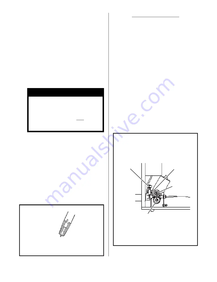
WIRE FEED PRESSURE ROLL ADJUST-
MENT
The wire feed pressure roll is
adjusted at the factory, prior to
delivery. It may be necessary to
readjust the setting as components
"seat in" or when changing to a
different diameter wire. To check
for proper roll pressure, hold the
torch in one hand and pinch the wire
between two fingers of the other
gloved hand. Pull the torch trig-
ger. If the wire continues to feed
when firm pressure is applied to the
wire, the pressure roll adjusting
nut should be backed off until the
feed rolls start to slip. If the
wire will not feed with very little
pressure applied, the pressure roll
adjusting nut should be tightened.
FIG. 14. PRESSURE ROLL ADJUSTMENT
PRESSURE
ROLL ARM
PRESSURE ROLL
ADJUSTING NUT
PRESSURE
ROLL
DRIVE
ROLL
(continued on following page)
1/4"
STICK-OUT
FIG. 13. WIRE STICKOUT


