79
Accessories
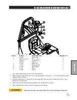
10-378 FOAM MARKER PARTS LIST
REF# PART#
DESCRIPTION
QUANTITY
REF#
PART#
DESCRIPTION
QUANTITY
2
16-987
Foam Nozzle Mounting Kit
1 per boom
3
15-507
Foamer Tubing
2
4
Clear Tubing
5
15-511
Foam Nozzle
2
6
Blue Tubing
7
15-510-01
Nozzle Mounting Rod
2
8
Boom
9
16-795
Square Clamp
4
INSTALLATION INSTRUCTIONS
1. Slide hose clamp onto drop tube of foam nozzle and attach restrictor bell.
2. Place splined end of Nozzle mounting rod (Ref 7) into top of foam nozzle (Ref 5). Tighten screw.
3. Slide two foam nozzle mounts (Ref 2) onto the rod. Place square clamps (Ref 9) on foam nozzle mounts and mount
the square clamps to the boom (Ref 8). Adjust foam nozzle mounts and clamps so nozzle assembly will clear end
of boom. Tighten foam nozzle mounts and square clamps to prevent side to side movement. Do the same to the
other side.
4. Being careful not to cut the tubing (Ref 3), cut the over-sleeve back approximately 2" (5 cm) to expose blue (Ref 6)
and clear tubing (Ref 4).
5. Remove blue wing nut from top connector of foam nozzle and slide it on the blue tube with the threads facing
toward end of tube. Slide blue tube all the way over the top of the small tube on foam nozzle. Slide wing nut back to
the threads and hand tighten. Follow the same steps for the clear tube and tube nut.
6. Route the tubing along underside of main frame using tie downs as necessary.
7. Install opposite ends of air-liquid tubes to compressor, again cutting back the over-sleeve approximately 2" (5 cm)
and inserting blue and clear tubes for the left boom section into the tubing connectors on the right side of compres
-
sor as far as possible.
8. Follow the same steps for the right boom tubing. Notice the right boom is inserted into left side of compressor. To
release tubing from compressor, hold black ring around tubing, and pull tube out.
9. Hose's must be routed along the side of the boom square tubing.
10. Mark 6 inches in from inside edge of foamer nozzle mounting bracket on square boom tubing.
11. Cut cable and strip casing, allowing enough length to connect to fuse block.
12. Strip and connect slide on connectors to each wire and use the heat shrink.
13. Connect black negative (-) wire to the ground and connect red wire to the positive (+).
14. Insert 10 amp fuse into slot which red wire was attached to.
Содержание 100684
Страница 12: ...10 Diagrams WIRING DIAGRAM Use dielectric grease on all electrical connections ...
Страница 14: ...12 Diagrams HYDRAULIC DIAGRAM ...
Страница 16: ...14 Parts MAIN BODY DRAWING ...
Страница 18: ...16 Parts CONTROL PANEL DRAWING ...
Страница 20: ...18 Parts FRONT AXLE DRAWING ...
Страница 22: ...20 Parts SEAT CONSOLE AND ROPS DRAWING ...
Страница 24: ...22 Parts FUEL TANK DRAWING ...
Страница 26: ...24 Parts OIL TANK OIL FILTER OIL COOLER DRAWING ...
Страница 28: ...26 Parts FOOT PEDAL LINKAGE DRAWING ...
Страница 30: ...28 Parts PUMP DRAWING ...
Страница 32: ...30 Parts ENGINE AND SPRAY PUMP DRAWING ...
Страница 34: ...32 Parts PARK BRAKE DRAWING ...
Страница 36: ...34 Parts REAR AXLE DRAWING ...
Страница 38: ...36 Parts TANK DRAWING TURBO QUAD AGITATOR DRAWING ...
Страница 40: ...38 Parts 15 301 ORBITROL DRAWING ...
Страница 42: ...40 Parts 45 373 DDC20 PISTON PUMP DRAWING ...
Страница 53: ...51 Accessories NOTES ...
Страница 54: ...52 Accessories 17 835 BOOM DRAWING ...
Страница 65: ...63 Accessories NOTES ...
Страница 68: ...66 Accessories 16 906 ELECTRIC HOSE REEL DRAWING ...
Страница 70: ...68 Accessories 16 129 MANUAL HOSE REEL DRAWING ...
Страница 80: ...78 Accessories FOAMER NOZZLE MOUNT HOSE GUARD MOUNT DRAWING ...
Страница 82: ...80 Accessories 14 291 FOAMER REPLACEMENT PARTS ...
Страница 88: ...86 Accessories 15 620 CHEMICAL CLEAN LOAD DRAWING ...


