9
Ser
vice
ADJUSTMENTS
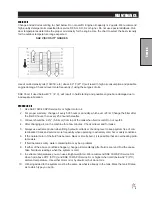
WHEEL CREEP
"Creep" is when the engine is running and hydrostatic transmission is in neutral, but due to inadequate align
-
ment, wheels still move. Do the following
procedure to stop this motion.
1. Lift up and support machine so rear
wheels are off the ground and can
turn freely.
2. On top of the pump there is a Creep
arm. Loosen bolt (Ref A) on creep
arm.
3. With engine running, adjust the 'creep
arm' side to side so centering arm
centers on the swash plate.
4. Tighten all fasteners and test by using
foot pedal linkage to see that 'creep'
is removed.
5. Turn engine off and lower machine.
PARK BRAKE
Turn knob clockwise on end of park brake to tighten. Turn it counter clockwise to loosen. If
finer adjustment is needed turn clevis on brake cable to adjust length of cable.
SPRAY PUMP
Located to the rear and right of the engine. Should have approximately
1
/
2
" (13mm) of deflection in the center
of the top strand. Loosen two
9
/
16
x 1
3
/
4
bolts. Slide pump to the rear to desired tension. Tighten two
3
/
8
x 1
1
/
2
bolts.
MASTER BOOM SWITCH (FOOT SWITCH)
The master boom switch, located on the left floorboard is used to override the master
switch on the computer console of the Radion 8140 spray system. By pushing down it
will turn on/off the booms.
SPRAY BOSS CONTROL HANDLE (ORANGE)
This lever located on the left side of the seat engages and disengages the
speed boss. Forward is engage and all the way back is disengage. When the
lever is engaged it sets a stop for the accelerator. The accelerator pedal must
be used to maintain this speed. To adjust speed use the knob on the end of
the lever, counter clockwise increases speed and clockwise decreases speed.
Disengage the lever and you will have full accelerator pedal range.
Содержание 100684
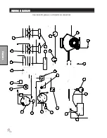
Страница 12: ...10 Diagrams WIRING DIAGRAM Use dielectric grease on all electrical connections ...
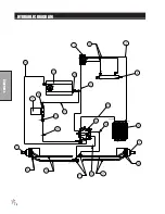
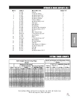
Страница 14: ...12 Diagrams HYDRAULIC DIAGRAM ...
Страница 16: ...14 Parts MAIN BODY DRAWING ...
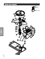
Страница 18: ...16 Parts CONTROL PANEL DRAWING ...
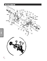
Страница 20: ...18 Parts FRONT AXLE DRAWING ...
Страница 22: ...20 Parts SEAT CONSOLE AND ROPS DRAWING ...
Страница 24: ...22 Parts FUEL TANK DRAWING ...
Страница 26: ...24 Parts OIL TANK OIL FILTER OIL COOLER DRAWING ...
Страница 28: ...26 Parts FOOT PEDAL LINKAGE DRAWING ...
Страница 30: ...28 Parts PUMP DRAWING ...
Страница 32: ...30 Parts ENGINE AND SPRAY PUMP DRAWING ...
Страница 34: ...32 Parts PARK BRAKE DRAWING ...
Страница 36: ...34 Parts REAR AXLE DRAWING ...
Страница 38: ...36 Parts TANK DRAWING TURBO QUAD AGITATOR DRAWING ...
Страница 40: ...38 Parts 15 301 ORBITROL DRAWING ...
Страница 42: ...40 Parts 45 373 DDC20 PISTON PUMP DRAWING ...
Страница 53: ...51 Accessories NOTES ...
Страница 54: ...52 Accessories 17 835 BOOM DRAWING ...
Страница 65: ...63 Accessories NOTES ...
Страница 68: ...66 Accessories 16 906 ELECTRIC HOSE REEL DRAWING ...
Страница 70: ...68 Accessories 16 129 MANUAL HOSE REEL DRAWING ...
Страница 80: ...78 Accessories FOAMER NOZZLE MOUNT HOSE GUARD MOUNT DRAWING ...
Страница 82: ...80 Accessories 14 291 FOAMER REPLACEMENT PARTS ...
Страница 88: ...86 Accessories 15 620 CHEMICAL CLEAN LOAD DRAWING ...


