background image

C H A P T E R   2

Installing your SMART Audio system

10

|

1012080 Rev A1

Installing the room module

Install the room module mounting plate on the ceiling or on a ceiling tile, and then attach the 

room module and the cable cover to the mounting plate.

WARNING

Take appropriate safety precautions when working at ceiling height, and use a sturdy 

ladder to reduce the risk of personal injury.

Installing the room module mounting plate

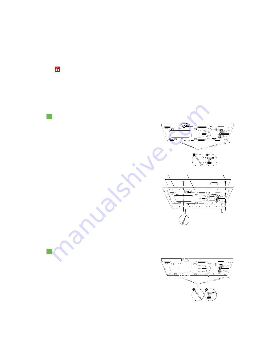
Install the room module mounting plate on the ceiling or on a ceiling tile.

To install the mounting plate on a ceiling tile

1.

Using the room module tile bridge as a template, 

mark the screw holes and the cable hole on the 

ceiling tile you previously removed for the room 

module.

2.

Drill the screw holes at the marks. 

3.

Cut out the traced cable hole with a drywall saw.

4.

Place the ceiling tile on the mounting plate, and 

then place the tile bridge on the ceiling tile, 

ensuring that you align the tile bridge with the 

mounting plate.

5.

Screw the included screws through the holes in 

the mounting plate, the ceiling tile and the tile 

bridge.

6.

Replace the ceiling tile, passing the wires and 

cables through the cable hole.

To install the mounting plate directly on the ceiling

1.

Place the room module mounting plate against 

the ceiling where you plan to install it, and then 

mark the screw holes with a pencil.

2.

Lower the mounting plate from the ceiling, and 

then drill holes at the marks.

Tile bridge

Ceiling tile

Mounting plate

Содержание Adio 340

Страница 1: ...SMART Audio 340 Classroom amplification system Installation guide...

Страница 2: ...case the user will be required to correct the interference at his own expense Trademark Notice SMART Board SMART Notebook SMART Audio smarttech the SMART logo and all SMART taglines are trademarks or...

Страница 3: ...speakers 7 Installing wall speakers 9 Installing the room module 10 Installing the control unit 13 Installing the microphone charging cradle 17 Chapter 3 Integrating your SMART Audio system with your...

Страница 4: ...ii 1012080 Rev A1...

Страница 5: ...Power cable Room module Mounting plate Cable cover Ceiling speakers Cut out template Tile bridge Adhesive putty Wire hook Wall speakers Wall speaker mounting bracket Power supply Mounting plate Cover...

Страница 6: ...s throughout the room to ensure even sound distribution See page 7 for installation instructions Choosing locations for wall speakers Install two speakers at the front of the audience and two speakers...

Страница 7: ...he presenter can easily access it Select a location that is within 8 2 4 m of a power outlet and within 50 15 2 m of cable distance from the room module See page 13 for installation instructions Choos...

Страница 8: ...E T Room module See page 10 Control unit See page 13 Ceiling speakers 4 See page 7 Wall speakers 4 See page 9 SMART Board interactive whiteboard system projector See page 19 Optional secondary audio d...

Страница 9: ...and speakers to reduce the risk of fire Take appropriate safety precautions when working at ceiling height and use a sturdy ladder to reduce the risk of personal injury To install speaker wires 1 Remo...

Страница 10: ...location IMPORTANT The maximum length of Cat 5e cable is 50 15 2 m Using longer Cat 5e cables can cause reduced performance To install cables for optional room module expansion sensors 1 Remove a ceil...

Страница 11: ...in a ceiling tile for the ceiling speaker 1 For each ceiling tile you removed while installing speaker wires place the ceiling speaker cut out template in the middle of the tile and then trace the ou...

Страница 12: ...not over tighten the clamp screws to the point where you damage the clamps or the ceiling tile 6 Connect the positive speaker wire to the red connector on the speaker and connect the negative speaker...

Страница 13: ...lan to install it and then mark the screw holes with a pencil IMPORTANT To prevent audio feedback install the speakers 5 1 5 m from the floor 3 Move the bracket away from the wall and then drill holes...

Страница 14: ...the cable hole on the ceiling tile you previously removed for the room module 2 Drill the screw holes at the marks 3 Cut out the traced cable hole with a drywall saw 4 Place the ceiling tile on the mo...

Страница 15: ...res cables and safety tether To attach the room module to the mounting plate 1 Position the room module so the cable connectors are facing the cabling area and then attach the room module to the mount...

Страница 16: ...5e connector to the room module connector on the control unit 4 If you have a paging system connect the existing paging wires to the paging input on the room module NOTES For more information on custo...

Страница 17: ...t the wall where you plan to install it and mark the screw holes on the wall with a pencil If you re pulling cables through the wall trace the cabling hole as well 2 Lower the control unit from the wa...

Страница 18: ...connect the RCA cable with two connectors on each end from your projector to the Aux In 1 connectors NOTE The Aux In 1 input is a mono input not a stereo input 5 If you have a secondary audio device...

Страница 19: ...en mark the anchoring holes on the wall with a pencil 2 Lower the bracket from the wall and then drill holes at the marks 3 Screw the mounting plate to the wall with the included screws and drywall an...

Страница 20: ...CHAPTER 2 Installing your SMART Audio system 16 1012080 Rev A1 6 Push the cables into the cable slots in the mounting bracket 7 Attach the power supply cover to the bracket Cable slot Cable slot...

Страница 21: ...o install it and then mark the screw holes with a pencil 2 Lower the mounting plate from the wall and then drill holes at the marks 3 Screw the mounting plate to the wall using the included screws and...

Страница 22: ...CHAPTER 2 Installing your SMART Audio system 18 1012080 Rev A1...

Страница 23: ...rojector to the Aux 1 In connectors on your SMART Audio system s control unit 2 Disconnect the 3 5 mm stereo cable from your interactive whiteboard system s extended control panel SMART software Your...

Страница 24: ...ART Board interactive whiteboard system 20 1012080 Rev A1 4 If your computer doesn t have SMART Notebook software installed place the included SMART Notebook software CD in your computer 5 Follow the...

Страница 25: ...pment and Battery regulations WEEE and battery directive Electrical and electronic equipment and batteries contain substances that can be harmful to the environment and to human health The crossed out...

Страница 26: ......

Страница 27: ......

Страница 28: ...SMART Technologies smarttech com support smarttech com contactsupport 1012080 Rev A1...

Отзывы: