C H A P T E R 2
Installing your SMART Audio system
12
|
1012080 Rev A1
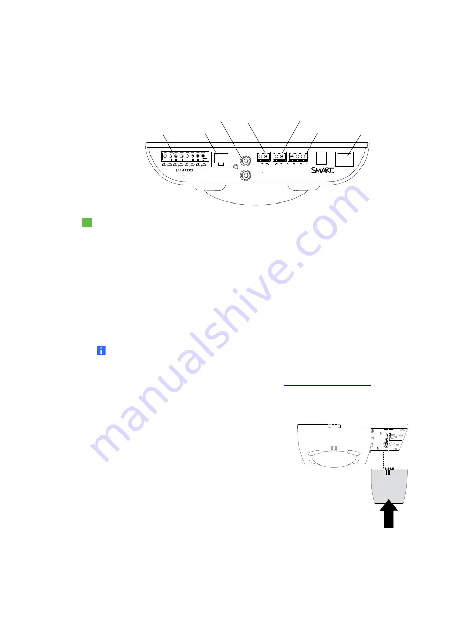
Connecting cables to the room module
For more information, see the
SMART Audio system cabling diagram
Room module connectors
To connect cables to the room module
1.
For each of the four speakers, connect the positive speaker wire from the red connector
on the speaker to a positive connector on the room module.
2.
For each of the four speakers, connect the negative speaker wire from the black
connector on the speaker to a negative connector on the room module.
3.
Connect the Cat 5e cable from the Cat 5e connector to the room module connector on the
control unit.
4.
If you have a paging system, connect the existing paging wires to the paging input on the
room module.
NOTES
–
For more information on customizing the 6-12 V DC input, the relay output and the
way pages play over the SMART Audio system, see the
SMART Audio 340
Classroom Amplification System User’s Guide
(
).
–
The Relay output has 3 states: NC (normally closed), COM (common) and NO
(normally open).
5.
After you connect the cables, attach the cable cover to
the mounting plate.
PAG I NG
IN PUT
6- 12V D C
IN PUT
NI
NI
T O C U
R EL AY
O UTPU T
N .C.
N .O.
C O M
Bus
Expansion
Sensors
Speaker wire connectors
Bus
Expansion sensors connectors
Paging input
General purpose 6-12 V DC input
Relay output
Cat 5e connector
Содержание Adio 340
Страница 1: ...SMART Audio 340 Classroom amplification system Installation guide...
Страница 4: ...ii 1012080 Rev A1...
Страница 22: ...CHAPTER 2 Installing your SMART Audio system 18 1012080 Rev A1...
Страница 26: ......
Страница 27: ......
Страница 28: ...SMART Technologies smarttech com support smarttech com contactsupport 1012080 Rev A1...


