210
SJ82 T, SJ86 T
229040ABA
Section 5 – Procedures
Boom
5.4-27 Lift Cushion Limit Switch (LS6)
LS6 slows the raising boom speed before the main lift
cylinder reaches the stop at full extension.
LS6 is normally closed. As the lift cylinder approaches
full extension, the switch roller makes contact with
the master cylinder link. The switch trips to open the
circuit.
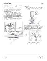
LS6 is located on the inside of the turret on the left-
hand side, near the lower end of the master cylinder
link.
M62348AA
LS6 location inside turret
WARNING
Ensure there are no personnel or obstructions in
the test area and there is sufficient room to raise
the boom.
Check Switch Operation:
1.
Position the main boom horizontal. Use a level
to verify.
2.
Place a digital protractor on a clean surface on
the underside of the main boom. Calibrate it to
0° (horizontal).
3.
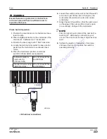
Locate the terminal strip inside the base control
panel. Set the multi-meter to
continuity-check
mode.
4.
Place the multi-meter probes on terminal
positions (
19 black/white
) and (
09 black
). The
multi-meter should show the circuit is closed
(continuity).
Black/White
Black
09
19
M62346AA
09
19
LS6 terminal connections
5.
Raise the boom up all the way until the lift
cylinder is fully extended. Observe if speed
slows (LS6 has tripped) when the boom angle
reaches 57°.
6.
Check the multi-meter reading. There should be
no continuity when the switch trips.
To
order
go
to
Discount-Equipment.com


