144
SJ82 T, SJ86 T
229040ABA
Section 4 – Troubleshooting Information
Electrical System
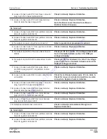
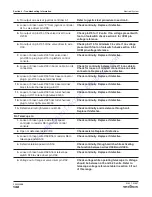
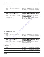
4.2-17 Direction Sensing Inoperative
1.
Loose or broken wire #09 from base terminal
block to limit switch LS1.
Check continuity. Replace if defective.
2.
Open or defective limit switch LS1.
Adjust limit switch if required. Check continuity
through switch. Replace if defective.
3.
Loose or broken wire #17 from limit switch LS1
to base terminal block.
Check continuity. Replace if defective.
4.
Loose or broken wire #17 from base terminal
block to base plug B pin #6.
Check continuity. Replace if defective.
5.
Loose or broken wire #17 in boom cable B or its
connectors.
Check for continuity between pins #6 on cable B.
Check for loose or corroded connections on cable
connectors. Replace if wire is defective.
6.
Loose or broken wire #17 from base plug B pin
#6 to valve driver pin #15 in platform control
console.
Check continuity. Replace if defective.
7.
Defective valve driver channel input for direction
sense enable.
See section 5 for OCM pin voltage reference.
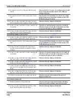
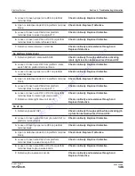
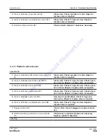
4.2-18 Steer Direction Sensing Inoperative
1.
No output on valve driver pin #4 to wire #17A.
Check pin #4 for 12 volts. If no voltage present
with foot on footswitch check section 5 for OCM
pin voltage reference.
2.
Loose or broken wire #17A from valve driver pin
#4 to relays 17ACR1 and 17ACR2.
Check continuity. Replace if defective.
3.
Loose or broken wire #02 from platform terminal
block to relays 17ACR1 and 17ACR2.
Check continuity. Replace if defective.
4.
Defective relays 17ACR1 and 17ACR2.
Check relay. Replace if defective.
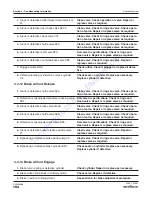
NOTE
If only one relay is bad and one is OK, you will have steer in one direction only.
To
order
go
to
Discount-Equipment.com


