207
SJ82 T, SJ86 T
229040ABA
Boom
Section 5 – Procedures
WARNING
Ensure there are no personnel or obstructions
in the test area and there is sufficient room to
reposition the boom.
Check Switch Operation:
1.
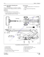
Position the main boom so it is horizontal. Use a
level to verify.
2.
Place a digital protractor on the underside of the
main boom. Calibrate it to 0° (horizontal).
3.
Position the boom angle at 57° from horizontal.
4.
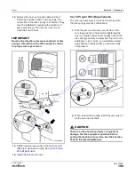
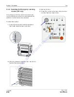
Locate the terminal strip inside the base control
panel. Set the multi-meter to
continuity-check
mode.
5.
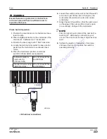
Place the multi-meter probes on terminal
positions shown below (as equipped):
Automatic platform
load sensing
(CE machines)
Wire 121 Black/White
and 09 Black
Standard load sensing
(ANSI machines)
Wire 121 Black/White
and 09B Black
Black
09
Black
09B
Black/White
121
M62360AA
09
121
09B
(ANSI)
(CE)
LS4 terminal connections
6.
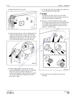
Loosen the switch and move it so that the switch
arm roller is just off the cam. At this point, the
multi-meter should show the circuit is closed
(continuity).
7.
Adjust the switch position so that the roller is just
on the edge of the cam and the circuit is open
(no continuity). Verify with the multi-meter.
NOTE
The LS4 roller should not fall off the cam before
reaching 57°. Additionally, continuity may not
occur in the circuit until the boom angle reaches
58.5°.
8.
Tighten the switch in this position, then raise
and lower the boom to confirm the switch is
operating correctly.
To
order
go
to
Discount-Equipment.com


