Skookum SK720 Скачать руководство пользователя страница 11

©2010 Skookum Robotics, Ltd    

21 


11  Gyro Setup Using the USB Interface 

CAUTION:  Do  not  connect  the  swashplate  or  tail  servos  to  the  gyro  until 
after the  SK720  has  been  configured  for your  servos. Your  servos  could  be 
damaged by an incorrect configuration. 

Note: The PC Setup Software has built-in Wizards to guide you through 
these  set  up  steps  as  a  first-time  user.  We  suggest  that  you  try  out  all 
three Wizards before reading further. 


Step 1: Connecting 


Start  the  SK720  setup  software  on  your  PC.  See  Section  10  of  this 

manual for instructions on how to install the setup software on your PC. 


Set your radio’s transmitter so Aileron, Elevator, and Pitch (Collective) 

are  output  each  on  a  separate  channel  (“Normal”  or  “1-Servo” 
swashplate mode). Also center all the trims and subtrims. 


The initial setup will be easier if you use a straight-line pitch curve and 

no  expo  or  dual  rates  in  your  radio. These  features  can  be  set  up  later, 
according to your usual preferences. 


Connect  the  SK720  to  your  PC  using  the  included  USB  cable.  The 

SK720  setup  software  will  automatically  detect  that  the  gyro  is 
connected to  your computer. Check that the connection indicator in the 
upper left is green and says 

Connected


Good  starting  points  for  the  cyclic  and  tail  gains  can  be  found  in  the 

“Default”,  “Scale” or  “Basic_3D” setup files, all of  which  are included 
with the PC setup software. Use the 

Load Setup

 option under the SK720 

setup  software’s 

File 

menu  to  load  a  default  file.  Modify  these  default 

setups to suit your own helicopter per steps 2 through 5 below. 

WARNING:

 All the control input and sense directions set up in Steps 2 

through 5 below must be correct or your helicopter will instantly crash if you 
try to fly it. Follow these steps carefully and complete the pre-flight check 
outlined in Section 13 of this manual before flying your helicopter. 


WARNING:

 Do not use any of the “Default”, “Scale”, or “Basic_3D” setup 

files mentioned above without first modifying them to suit your helicopter per 
Section 11, Steps 2 through 5. 


©2010 Skookum Robotics, Ltd    

22 


Step 2: Match the Gyro to Your Transmitter 


Click the 

Control

 tab in the 

Offline Setup Values

 area in the lower half 

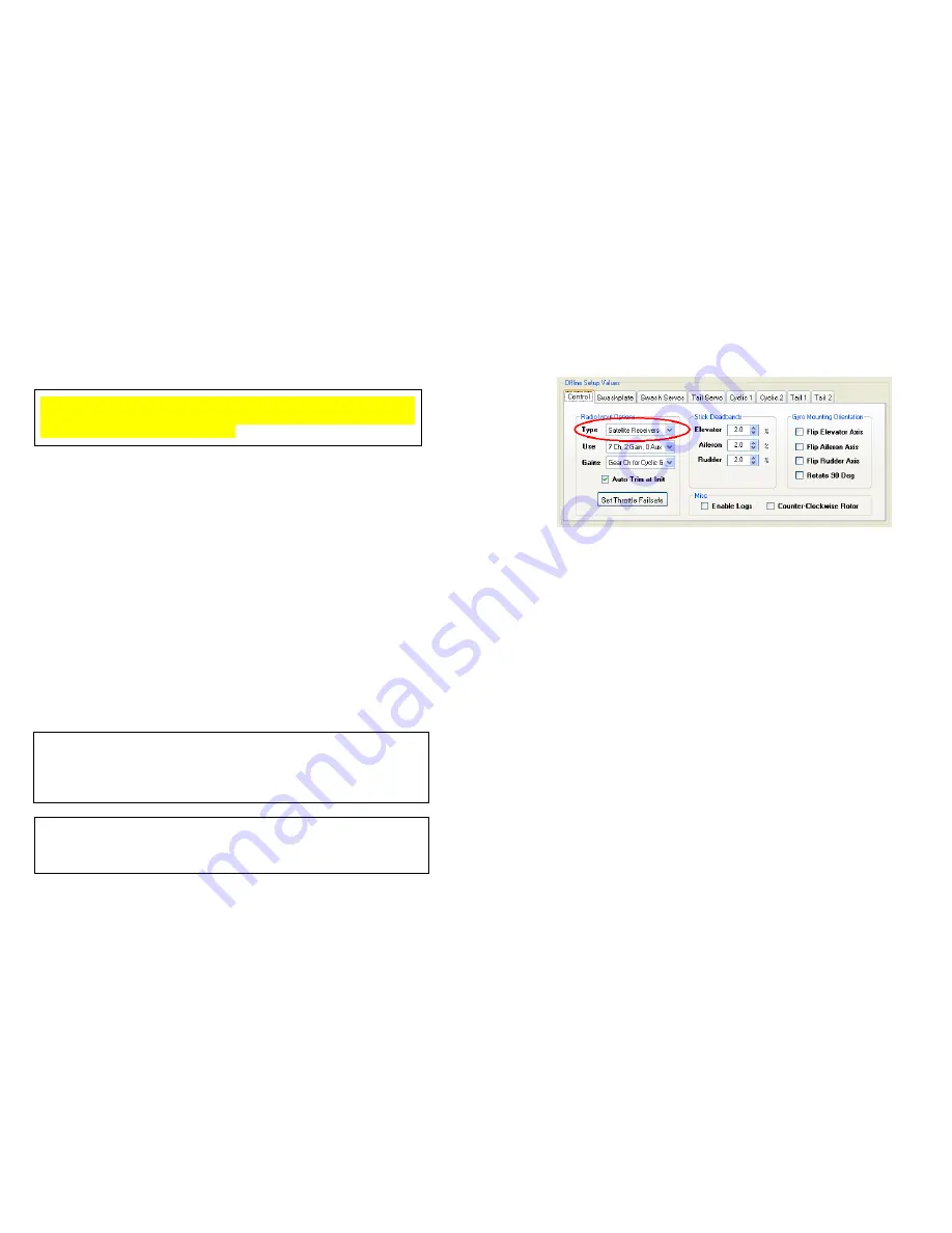
of the setup software window (see Figure 11.1 below). Select whether or 
not you will be using satellite receivers.  


Figure 11.1 – Selecting Receiver Type 


Satellite receivers can be bound using the SK720’s bind mode. Enable 
the bind mode from the 

Utility

 menu on the setup software by selecting 

Bind Sat RX’s on Power Cycle

. Selecting this option will cause all 

connected satellite receivers to enter bind mode the next time that the 
SK720 is power cycled (i.e. turned off and then on again).  


Click the 

Send Setup

 button, or press the F1 key to set the changes on 

the gyro. 

You must SEND the setup whenever you want to test 

changes.


Cycle the SK720’s power and wait ten seconds. Check 

Inputs from 

Receiver 

again. The % values for Elevator, Aileron, and Pitch, and 

Rudder should be close to zero. 


Try moving the elevator stick towards you (nose up) and look at the 
Pilot Control field under Elevator. The number displayed should be 
close to 100% and should be shown on a 

green 

background. If it is 

negative and displayed on a 

red

 background, reverse that channel in 

your radio. If it’s too low or reaches 100% much before the stick’s limit, 
adjust the endpoints (ATV’s) for that channel in your transmitter. 
Typical end point (ATV) values will be near 125% for JR/Spektrum 
radios.   


Repeat for Aileron and Rudder inputs, but move the sticks right (

green

).  

Then check the collective pitch input, moving the stick up (

green

). 

Again reverse and/or alter the end point values as necessary. 


Содержание SK720

Страница 1: ...ety 6 5 Setup Overview 7 6 Mounting the Gyro 9 7 Helicopter Airframe Setup 11 8 Connections 13 9 Modes Indicators and Power Up 16 10 Installing the Windows Setup Software 17 11 Gyro Setup Using the US...

Страница 2: ...s well as mCCPM swashplates Works with 2 3 4 or 5 blades because phase is adjustable Swash Ring anti binding algorithm Expansion port for future accessories such as GPS Optional 20 amp external power...

Страница 3: ...on how to install the SK720 s Windows setup software See Section 11 of this user s manual for a detailed description of how to set up your new SK720 gyro 2010 Skookum Robotics Ltd 6 4 Safety An R C h...

Страница 4: ...lp of the initial configuration wizard Also see Steps 2 and 3 in Chapter 11 of this manual 6 Check for correct sensor readings with the help of the initial configuration wizard Also see Chapter 11 Ste...

Страница 5: ...unit Ideally use a cable sleeve because this maintains a neat appearance while allowing the cables to move relative to one another 2010 Skookum Robotics Ltd 10 We strongly recommend using the Skookum...

Страница 6: ...uch blade pitch action when setting up a rotorhead mechanism originally designed for helicopters with a flybar Either servo travel or servo arm length will also need to be reduced to allow normal gain...

Страница 7: ...k up using a battery or BEC In satellite receivers mode the SK720 also outputs the throttle channel on port IO A T as well as up to three additional auxiliary outputs for such things as a governor lan...

Страница 8: ...in this mode the indicator LED will slowly flash green In Flight mode the LED Indicator will show solid red while the SK720 initializes and will turn solid green once the SK720 is ready to fly The SK7...

Страница 9: ...gram Installation Options Screen There are six check boxes available and all but the SK720 Digital Flybar GUI checkbox can be selected on or off It is recommended that you install all of the available...

Страница 10: ...tware will automatically detect the gyro The Connected indicator in the setup software should turn green and the gyro s serial number and firmware revision should also be displayed See Figure 10 4 bel...

Страница 11: ...t Follow these steps carefully and complete the pre flight check outlined in Section 13 of this manual before flying your helicopter WARNING Do not use any of the Default Scale or Basic_3D setup files...

Страница 12: ...e Rudder yaw axis but slowly rotate the helicopter to the right The Gyro Rate for Rudder should be positive and show green If not select Flip Rudder Axis on the Control Figure 11 2 Setting Gyro Mounti...

Страница 13: ...prevents unwanted interaction at max and min collective Increase the servo travels instead if you need more motion Step 6 Tail Setup Figure 11 5 Offline Setup Values Tail Servo Tab Click the Tail Ser...

Страница 14: ...elected The endpoint on the channel will set the gain for that function 50 is a safe starting point for both5 By default for the tail Bank 1 is Heading Hold mode and Bank 2 is Rate Mode 5 For users of...

Страница 15: ...l Phasing 3 Now try full nose up elevator control with aileron centered Measure the pitch of the blade that extends over the nose 2010 Skookum Robotics Ltd 30 4 The blade should not change pitch if th...

Страница 16: ...Ltd 32 14 Flight with the SK720 Gyro In flight mode the swashplate will not respond to the controls directly Its action will be similar to a heading hold tail gyro After it has been static for a few s...

Страница 17: ...from any orientation including upside down But SK720 will not automatically adjust the collective You will need to manually adjust the collective during a recovery and the helicopter may loose signif...

Страница 18: ...uning banks For each of those banks fly the helicopter as you normally would for at least four flights Use the SK720 setup software to disable self tuning once the gains stop changing significantly 7...

Страница 19: ...steps If the nose goes down increase the Elevator value by 1 or 2 steps If the helicopter banked the right or left you may also have to adjust tail drag compensation for Aileron If it banked right dec...

Страница 20: ...white and gray progress bar may also be used to control playback You can jump forward or backwards in the playback sequence by clicking on the progress bar with your mouse Figure 18 2 on the followin...

Страница 21: ...again Reset Log Counter When flight logging is enabled see the Control Tab section below selecting this option causes the log index number to be reset to zero Thereafter log file names will be LOG0 BI...

Страница 22: ...ns in your helicopter See Section 10 Step 3 for details on how to use these options 2010 Skookum Robotics Ltd 44 Swashplate Tab The Swashplate tab is found in the Offline Setup Values region of the ma...

Страница 23: ...evenly to the maximum rate of the centre servo 2010 Skookum Robotics Ltd 46 Servo Speed Take this value from your servo manufacturer s specifications Units are in seconds per 60 degrees of motion Thi...

Страница 24: ...wind gusts This feature gives the heli a locked in feel Slop free linkages rigid rotor head mechanics stronger servos and stiff blades allow higher gains here When hiller gain is too high the heli wil...

Страница 25: ...The response of the tail blades to the error in rate of motion This is the tail s primary gain Hold Gain The response of the tail blades to accumulated tail position error This allows the gyro to trim...

Страница 26: ...or tilts at one particular rpm Vibration effects on the gyro Make sure it is mounted on good damping tape and doesn t contact the frame Also check for tail rotor vibration Can not set Hiller very hig...

Страница 27: ...ibration is getting into the unit Make sure its case isn t contacting the heli s frame and the wires leading to it are a bit loose For larger helicopters you may want to use a separate power bus to al...

Страница 28: ...pdate process may fail if you do making the unit into a paperweight Your SK720 would then need to be returned to Skookum Robotics for servicing 2010 Skookum Robotics Ltd 56 Appendix C Warranty and Tec...

Отзывы: