background image

39

The LED light will be damaged if the connections 
of the cables at the terminals of the connector are 
accidentally reversed (see diagram Fig.5.5) 

5.3.1 

FUSE AND ELECTRICAL DIAGRAM  


The fuse is located on one side of the control box and can be accessed by unscrewing the protective cap. 
 

Before replacing the fuse, check with expert personnel that there are no short circuit contacts in 
the electrical circuit in Figure 5.5. 

The cable for the solenoid valve has a connector with an 
LED light that turns on when current is passing through 
(Fig.5.4). 
 

If the LED light on the solenoid connector does not turn on: 
 

1)  check that there is power at the tractor plug. 
2)  check that the fuse is good  
3)  the LED light is damaged  
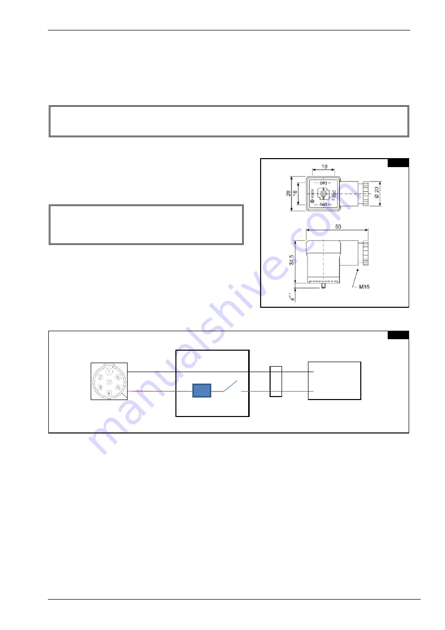
 

5.4

5.5

PIN 1 GND

PIN 7 POWER SUPPLY

FUSE 5A

SWITCH

PIN 1  DIN CONNECTOR

PIN 2  DIN CONNECTOR

TRACTOR PLUG

CONTROL BOX

PLUG

VALVE CONNECTOR

Содержание QRX 12

Страница 1: ...ASSEMBLY USE AND MAINTENANCE QRX 12 14 201600 ...

Страница 2: ......

Страница 3: ..._______________________28 4 7 CENTER RAKE WHEEL KIT OPTIONAL ___________________________________________29 4 8 ASSEMBLY OF CONVERSION KIT FROM QRX12 TO QRX14 __________________________33 4 9 GREASING POINTS ____________________________________________________________35 SECTION 5 ADJUSTMENT PREPARATION AND USE ______________________________________36 5 1 HITCHING THE MACHINE TO THE TRACTOR_________...

Страница 4: ...ble to return the defective part to the manufacturer the manufacturer cannot be held liable for any costs due for repair or replacement of any part of the machine The manufacturer shall only supply the part s required for such repair and or replacement The warranty shall be considered null and void when it is evident that the machine has been improperly used or has been repaired without authorizat...

Страница 5: ...to the operator and anyone within range of the machine 2 2 WARNING SIGNS Fig 2 1 Read carefully the user s manual and follow all the safety instructions Fig 2 2 Before doing any checking maintenance and or repair op erations stop in a suitable place turn off the tractor apply the brake remove the key from the ignition and consult this manual Fig 2 3 Warns against the potential and serious risk of ...

Страница 6: ...tractor and or on the machine Fig 2 6 Summarizes all the potential and serious dangers encountered during the assembly use maintenance and or repair of the ma chine Fig 2 7 Indicates the maximum speed allowed during road transport 19 MPH 30 Km h Fig 2 8 Recommends the wearing of suitable protective equipment and clothing to prevent injury when carrying out assembly use maintenance and repair opera...

Страница 7: ...that if not avoided could result in serious personal injury It also warns not to remove protective devices 2 4 INDICATION SIGNS Fig 2 11 Indicates the components to be assembled and or identified on the right or left side of the machine Fig 4 1 The RH and LH sides are determined by standing behind the machine and looking forward Fig 2 12 Indicates a greasing point 2 9 2 10 2 12 RIGHT LEFT 2 11 ...

Страница 8: ...um Transport Height B 9 2 2 8m 9 2 2 8m Tractor Requirements HP 50 36 7 KW HP 60 44 KW Tires 205 75 15 205 75 15 Transport Width C 9 2 2 8m 9 2 2 8m Transport Length A 23 9 7 24m 26 5 8 04m Tread Width D 8 1 2 48m 8 1 2 48m Weight 2855 lbs 1295 kg 3240 lbs 1470 kg Full optional 3 2 CHARACTERISTICS OF HYDRAULIC ELECTRIC COMPONENTS Power supply 12 V DC 7 pin connector ISO1185 3 pin connector DIN9680...

Страница 9: ...ONTAL DRAWBAR 5 LEFT FOLD UP CYLINDER 6 LEFT FOLD UP ARM 7 LEFT TELESCOPING ARM 8 LEFT TANDEM WHEEL AXLE 9 LEFT REAR SECTION 10 LEFT CENTR SECTION 11 LEFT FRONT SECTION 12 LEFT EXTENSION SECTION 13 LEFT RAKE WHEEL ARM 14 LEFT RAKE WHEEL 15 LEFT SPECIAL RAKE WHEEL ARM 16 CENTER RAKE WHEEL KIT optional 17 SPRING ASSEMBLY 3 1 ...

Страница 10: ...ne is identified by the following data Machine type Serial number Year of manufacture WEIGHT stamped on the nameplate attached to the machine frame and to be specified when requesting spare parts or information Optional Center rake wheel kit Spa ...

Страница 11: ...components are inspected by the manufacturer before shipment Upon receipt of the machine check that the crate is intact and that the contents have not been damaged during shipment If any damage and or ir regularities are found report them immediately to your dealer Note The packaging is made from wood plastic film cardboard and steel and must be dis posed of according to applicable laws in your lo...

Страница 12: ...NS Examples of general measurements for identifying the assembly accessories based on type Fig 4 1 For tightening torques see the table below the class of the material is normally stamped on the head of the bolts Fig 4 2 4 1 4 2 ...

Страница 13: ...26 1 1 64 55 2 5 32 300 11 51 64 2 5 64 27 1 1 16 60 2 23 64 350 13 49 64 3 7 64 28 1 3 32 65 2 35 64 400 15 47 64 4 5 32 29 1 9 64 70 2 3 4 450 17 45 64 5 3 16 30 1 11 64 75 2 15 16 500 19 43 64 6 15 64 31 1 7 32 80 3 9 64 550 21 41 64 7 17 64 32 1 1 4 85 3 11 32 600 23 39 64 8 5 16 33 1 19 64 90 3 17 32 650 25 37 64 9 11 32 34 1 21 64 95 3 47 64 700 27 35 64 10 25 64 35 1 3 8 100 3 59 64 750 29 ...

Страница 14: ...port the crosspiece 1 with the forks of a forklift 4 Fasten the axle unit 2 to the hub 7 on the right side of machine see fig 4 4 using the bolts 5 and 3 the washers 4 for bolts 3 and nuts 8 5 Screw in grease nipple on hub 7 6 Repeat the same operations on the other side of the machine Item 3 4 bolts M16x130 5 8 x 5 7 64 DIN 931 UNI 5737 Item 4 4 washer ø16 ø48x4 ø5 8 ø1 7 8x5 32 Item 5 6 bolt M16...

Страница 15: ...em 1 8 bolts M16x140 5 8 x 5 DIN 931 Item 4 8 nuts M16 5 8 DIN 980 ONLY FOR THE QRX 14 STEP 3 With reference to Fig 4 5 carry out the operations in the following order Insert and connect the additional drawbar 2 be tween drawbars 1 and 3 fastening it with bolts 4 and nuts 5 Item 4 6 6 bolts M16x50 5 8 x 2 DIN 931 Item 5 6 6 nuts M16 5 8 DIN 980 4 4 4 5 QRX 14 ...

Страница 16: ... 5 Attach the manual canister 16 at point A on the drawbar 2 using the bolts 17 washers 18 and nuts 19 Note all the manuals and documents regarding the machine must be kept in the manual can ister 16 so that they may consulted at any time Item 3 6 bolts M16x50 5 8 x 2 DIN 931 Item 4 6 nuts M16 5 8 DIN 980 Item 6 2 pins ø25x124 1 x5 Item 7 2 washers ø12 36x2 5 ø15 32 1 27 64x 3 32 Item 8 2 bolts M1...

Страница 17: ...rease nipple 7 into its hole on the frame 2 3 Connect the fold up arms 2 to the frame 2 with the pin 5 and fasten all with the spring pin 5 4 Repeat the same operations on the other side of the machine Item 5 2 pins ø50x243 ø2x9 Item 6 2 spring pins ø12x70 ø1 2 x2 DIN 1481 Item 7 2 grease nipples M8 5 16 Item 4 4 plastic bushings ø50 60x50 2 2 3 8 x2 4 7 ...

Страница 18: ... Fig 4 9 carry out the operations in the follow ing order 1 Fasten the cylinder 1 on hitch point 5 with pin 2 washer 4 nut 3 The lever of valve of cyl inder 1 are content in accesso ries bag 2 Fasten the cylinder 6 with pins 7 spacer 8 washer 4 nut 3 Pay attention on position of valve 9 3 Repeat the same operations on the other side of the machine Item 2 n 2 pins ø20x60 ø25 32 x2 23 64 Item 3 n 4 ...

Страница 19: ...olts 19 and nuts 18 Insert the caps 21 in the sections 17 6 Attach the front section 20 to the main section 1 fastening it with the bolts 19 and nuts 18 7 Repeat the same operations on the other side of the machine Item 9 2 nylon bush ø85 75x30 ø3 11 32 2 15 16x1 11 64 Item 10 2 grease nipples M8 5 16 Item 3 2 bolts M24x170 15 16 x6 11 16 DIN 931 Item 5 2 pins ø75x107 ø2 15 16x4 14 64 Item 4 2 was...

Страница 20: ... the extension section 22 to the front section 18 fastening it with the bolts 19 and nuts 18 2 Insert the cap 21 in the extension section 22 3 Repeat the same operations on the other side of the machine Item 19 6 6 bolts M12x35 15 32 x1 3 DIN 933 Item 18 6 6 nuts M12 15 32 DIN 980 Item 21 2 plastic caps 4 11 QRX 14 ...

Страница 21: ...rations in the following order 1 Insert the plastic bushings 2 in all their seats 5 in the rake sections 2 Insert the arm 1 and fasten with the washer 3 and the spring pin 4 3 Attach the grease nipple 6 M6 in the threaded hole of the bushings 5 Item 2 24 28 plastic bushings ø35 42x26 ø1 3 8 1 41 64x1 1 64 Item 3 12 14 washers ø35 50x5 ø1 3 8 1 61 64x3 16 Item 4 12 14 spring pins 8x50 ø5 16 x1 61 6...

Страница 22: ...spring assembly A to the arm 2 with the self locking pin 1 2 Rotate until it clamps on to it Item 1 12 14 pins ø16x36 ø5 8 x1 13 32 STEP 11 With reference to Fig 4 15 carry out the operations in the following order Fasten the rake wheel 1 to the hub 2 with the bolts 3 washers 4 and nuts 5 Item 3 72 84 bolts M10x25 DIN 933 25 64 x1 Item 4 72 84 washers ø10 5 DIN 127B 27 64 Item 5 72 84 nuts M10 DIN...

Страница 23: ...to the machine lowering and raising them several times with the controls until the air is removed from the circuit These operations must take place in conditions of complete safety with the machine connected to the tractor and the operator sitting in the driver s seat making sure that no persons or objects are within the range of movement of the machine When using the system for the first time mak...

Страница 24: ...nd split washers 10 Pos Qty Description 1 6 WASHER 3 8 BONDED 2 2 REDUCTION MF 3 8 M 1 4 F 3 2 THREADED MALE EYE 1 4 4 2 PERFORATED HOLLOW SCREW FITTING 1 4 5 4 WASHER 1 4 BONDED 6 4 T FITTING 1 4 M F SWIVELING 7 2 ELBOW FITTING 90 M F 1 4 SWIVELING 8 4 REDUCTION NIPPLE 3 8 GAS 1 4 9 4 NUT M 8 5 16 DIN 980 10 4 SPLIT WASHER ø 8 4 ø5 16 DIN 127B 12 4 FLAT WASHER ø 8 4 ø5 16 DIN 125A 13 4 BOLT M 8 X...

Страница 25: ...hrottled nipple 6 and washer 1 to the valve 5 3 Attach the assembly thus obtained on the boss on the rake arm fold up cylinder shown in the figure using the bolt 3 and washers 1 4 Repeat the same operation on the other side of the machine Pos Qty Description 1 8 WASHER 3 8 BONDED 2 2 EYE FITTING 3 8 3 2 PERFORATED SCREW FITTING 3 8 4 2 THROTTLED NIPPLE 3 8 3 8 5 2 VALVE 3 8 6 2 NIPPLE 3 8 3 8 4 18...

Страница 26: ... the pairs of hoses so as to avoid having difficult crossing problems later on 2 In Fig 4 20 on the opposite side of the hydrau lic hoses 1 and 2 there is a male fitting 3 on which to place a 1 2 washer 4 and screw on the quick coupling 5 for the tractor valve Pos Qty Description 1 2 HOSE L 5850mm 19 2 5 16 FD MD 2 2 HOSE L 6000mm 19 8 7 32 FD MD 4 4 Washer 5 4 Quick coupling 6 8 DOUBLE SEMI COLLA...

Страница 27: ... 14 Screw the hoses 15 and 17 to the pair of T fittings 6 following the alignments shown in the figure 6 Extend the hose 1 on the left side of the machine up to the valve 14 having it pass in between hoses 15 and 17 and screw it onto the left fitting of the valve The blocks 8 must be in between hoses 1 7 Connect the remaining end of the hose 5 with screw 24 and washer bonded 23 to the right fold u...

Страница 28: ... arrangement of the hoses in pairs as shown in the figure 2 Connect hoses 2 to cylinder 9 with fittings 7 and washers 8 3 Connect hoses 1 to cylinder 6 with fittings 4 and washers 5 4 Repeat the same operations on the other side of the machine without tightening the bolts of blocks 12 Pos Qty Description 1 4 HOSE L 2200mm 7 2 39 64 F90 FD 2 4 HOSE L 2600mm 8 6 23 64 F90 FD 4 7 8 NIPPLE 5 8 8 WASHE...

Страница 29: ...o the valve 5 as shown in Fig 4 24 The hoses 1 2 3 and 4 must be the same in Fig 4 23 otherwise the hydraulic system will malfunction 2 Repeat the same operations on the other side of the machine When all of the assembly is completed check to make sure that the connections have been properly made Lastly fasten the hoses with the collars 4 24 4 23 ...

Страница 30: ...the electric cable 5 in Fig 4 26 along the machine drawbar 2 Screw connector 3 into the valve 5 with the bolt 4 in Fig 4 25 passing through the hydraulic hoses as shown in the figure 3 Fasten the cable 1 with the bands 2 along the hydraulic hoses of the machine drawbar 4 Place the control box 1 in Fig 4 26 in the trac tor cab using the bracket 3 5 Tighten the knobs 2 after having suitably ori ente...

Страница 31: ...the ground according to the desired working conditions Tighten the nuts 20 of the bolt 19 in Fig 4 27 to decrease the pressure on the ground Loosen the nuts 20 of the bolt 19 in Fig 4 27 to increase the pressure on the ground If the working conditions do not require the use of the center rake wheel close the valve 5 in Fig 5 26 after having positioned the rake wheel arm in the raised position To l...

Страница 32: ... the bolt 19 into the hole of the milled pin 13 8 Screw the nuts 20 onto the bolt 19 until a few millimeters of the threading protrude about 3 4mm The tension of the spring must be adjusted according to the desired pressure of the rake wheel on the ground 9 Fasten the rake wheel 23 to the arm 4 using the bolts 24 washers 25 and nuts 26 Pos Qty Description 2 4 BOLT TE M16 X150 5 8 x5 57 64 DIN 931 ...

Страница 33: ...ing 10 and the 3 8 female fitting to the throttling nipple 8 Position correctly the hose 9 so that it does not get deformed or crushed when the cylinder is operating Once this is done tighten all the various components that had been left un tightened earlier 4 Fasten the fitting 2 to the upper boss on the cylinder with the washer 1 5 Connect the valve 5 to the adaptor nipple 3 with the washer 4 6 ...

Страница 34: ...AIGHT FITTING M F SWIVELING 3 8 3 1 REDUCTION NIPPLE 3 8 1 4 4 3 WASHER 1 4 BONDED 5 1 VALVE 1 4 6 1 PERFORATED SCREW FITTING 1 4 7 1 HOSE L 730mm 28 47 64 FD OC 8 1 NIPPLE 3 8 3 8 THROTTLED 9 1 HOSE L 640mm 25 3 16 FD FD 3 8 10 2 CROSS FITTING 1 4 4 29 ...

Страница 35: ...the following order 1 Mount the extension 22 with the front section 18 and secure with screws 19 and nuts 18 2 Insert the plug 21 in the extension 22 3 Repeat the same procedure on the other side of the machine Item 19 6 6 screws M12x35 15 32 x1 3 DIN 933 Item 18 n 6 6 nuts M12 15 32 DIN 980 Item 21 n 2 plugs Before continuing the installation note The pair of arms right and left with locking hole...

Страница 36: ... 4 4 Install the nipple 6 M6 into the threaded hole of the bushings 11 5 Repeat the same procedure on the other side of the machine Item 2 n 4 plastic bush ø35 42x26 ø1 3 8 1 41 64x1 1 64 Item 3 n 2 washers ø35 50x5 ø1 3 8 1 61 64x3 16 Item 4 n 2 spring pins 8x50 ø5 16 x1 61 64 DIN 1481 Item 6 n 2 grease nipple M6 15 64 1 Loosen all the blocks 5 which support the pipelines 1 2 3 end 4 for their en...

Страница 37: ...rs Fig 4 33 Pivot pins of the rake wheel arms A Rake wheel arm suspension spring assemblies B Pins C D Every 40 forty hours Fig 4 33 wheel hubs E tandem axle hub F rake wheel hubs G At the beginning of each season Read the operator s manual Check the tire pressure Lubricate all greasing points Check the tightness of the wheel nuts with a tightening torque of 120 ft lbs 16 3 daNm 4 33 B E F D A G C...

Страница 38: ...2 Remove the pins 2 from the hitch 1 removing the washers 3 and bolts 4 3 Set the hitch 1 in the desired position moving it to the free holes 5 and fasten again with the pins bolts and washers used previously The hitch can be rotated from position E to position F to ob tain the best position 4 Connect the drawbar hitch 1 to the tractor hitch 6 with pins 7 8 of adequate shape and size It is importa...

Страница 39: ...r put the arms in the lowered position with the rake wheels on the ground to avoid having the machine unbalanced when unhitching it from the tractor 5 Remove the parking stand from the transport position 6 Install the stand in the parking position 7 Secure the stand in place with the pin with handle and clip 8 Turn the parking stand crank until the foot touches the ground and continue cranking unt...

Страница 40: ...and wind row width from the tractor valve using the electric selector in Fig 5 3 angulation extension To change the extension of the telescoping arm A move the tractor valve connected to the line of hoses of cylinders B after having selected the EXTENSION position on the remote control shown in Fig 5 3 To change the angle of the arm C move the tractor valve connected to the line of hoses of cylind...

Страница 41: ... expert personnel that there are no short circuit contacts in the electrical circuit in Figure 5 5 The cable for the solenoid valve has a connector with an LED light that turns on when current is passing through Fig 5 4 If the LED light on the solenoid connector does not turn on 1 check that there is power at the tractor plug 2 check that the fuse is good 3 the LED light is damaged 5 4 5 5 PIN 1 G...

Страница 42: ...vary depending on the model and coun try of origin The standard supplied is the 7 pin plug ac cording to ISO 1185 as in fig 5 6 Plug is available on request for 3 pin socket DIN 9680 The replacement of the plug is possible by making attention to the arrangement of the electrical polarity as in fig 5 6 5 6 ISO 1185 PLUG USA Ground pin 1 Positive pin 7 Positive pin 15 30 Ground pin 31 DIN 9680 PLUG ...

Страница 43: ...hen moving over rough ground that the sections do not touch the sides of the tractor with the risk of causing damage to both machines If there could be contact between the parts it is recommended that the angle of the sections be increased by means of the angle cylinder before raising the sections This brings the sections farther away from the trac tor and creates a situation of increased safety W...

Страница 44: ... are parallel to the ground by activating the tractor valve after selecting the ANGULATION position on the remote control in Fig 5 3 5 Close the cylinder valves in Fig 5 8 by turning the levers A for the right and left cylinders levers B for the right and left cylinders and lever C optional 6 Check that all safety signs and reflectors are installed clean and visible Danger of crushing Keep a safe ...

Страница 45: ...f the finished machine exceeds the legal size follow local regulations for the special transport of oversized equipment Before going on public roads 1 Check that the fold up arms are locked in place 2 Check that all valves are closed 3 Replace immediately any broken reflector panels or damaged signal lights For road use of the machine is available on request a light kit for road use depending on t...

Страница 46: ...Fig 5 9 by activating the tractor valve after selecting the ANGULA TION position on the remote control in Fig 5 3 6 Finish lowering the rake arms The machine is in working position The tractor hydraulic system must be set in floating mode during operation 5 7 ADJUSTING THE PRESSURE OF THE RAKE WHEELS ON THE GROUND The pressure of the rake wheels on the ground can be adjusted with the spring 1 Fig ...

Страница 47: ...ximum and minimum working and windrow widths Fig 5 11 MODEL QRX 12 QRX 14 Maximum Windrow Width 6 7 2m 6 7 2m Minimum Windrow Width 3 0 9m 3 0 9m Maximum Working Width 25 1 7 65m 28 8 5m Minimum Working Width 21 12 6 7m 24 11 7 6m 5 11 A B ...

Страница 48: ...sition check to make sure that there is no one within the operating range of the machine If someone is there make sure they move away out of range Configuration for working only on the left side Fig 5 12 Configuration for working only on the right side Fig 5 13 5 13 5 12 DANGER ...

Страница 49: ... Open the valves A and B of the side on which you wish to work 3 Return to the tractor and lower the arm with the hydraulic cylinder On the side in which the valves are closed the arm C will stay raised with the minimum extension Fig 5 14 4 Adjust the angle and extension of the rake arm used as desired The machine is ready to work on one side only 5 14 A B C ...

Страница 50: ...m in the raised po sition Fig 5 15 1 Unhook the spring assembly B removing the pin from the fork 2 Connect the fork to the plate C with the pin of the fork 3 Manually lift the arm A at the same time pull the spring knob D and leave it near the locking hole of the rake wheel arm A 5 15 ...

Страница 51: ...after repairs or maintenance make sure that the area is sufficiently ventilated to prevent the accumulating of noxious gases In order to acquire the necessary control and to work safely practice performing various maneuvers simulat ing those required in the field with the help of an expert 6 2 STORAGE FOR LONG PERIODS At the end of the season or when the machine will not be used for a fairly long ...

Страница 52: ...commercial solvents authorized by the competent authorities Do not use compressed air or high pressure water to clean the machine If this is unavoidable then wear glasses with lateral protection and limit the pressure as much as possible When work is finished inspect and check the machine completely with the machine disconnected from the tractor After the first 10 ten hours of use Check the tightn...

Страница 53: ... If the oil penetrates the skin it may cause serious injury Consult a physician immediately Before doing any adjustments maintenance or repair work lower the machine to the ground depressurize the hydraulic system turn off the engine remove the ignition key and wait until all moving parts have come to a complete stop 6 6 SCRAPPING THE MACHINE The machine consists mainly of ferrous material which m...

Страница 54: ...Zona Industriale Viale Grecia 8 06018 TRESTINA Perugia ITALY Tel 39 075 8540021 Telefax 39 075 8540523 e mail sitrex sitrex it www sitrex com ...

Отзывы: