background image

“Take up load” operating state

The holding force intensifies if the load moves further in the direction in which
it is to be secured. In doing so, the self-reinforcing clamping sleeve and hous-
ing brace themselves. The relative motion between rod and Safety Lock is
very low and does not amount to more than a maximum of 2 mm, even on
large sizes, with the admissible load M. The rod 

does not

 slip if there is an

overload. Loads must not exceed twice the admissible load M. To release
clamping after taking up the load, the rod is moved by the drive in the direction
opposite to the load direction and pressure is applied to pressure port L.

4.3   Layout

The Safety Lock may be integrated into the machine as a 

stationary

 compo-

nent or as a movable component 

moving with the load

:

• If the Safety Lock is integrated into the machine as a stationary compo-

nent, the load (e.g. the slide) is normally movable.

• If the Safety Lock moves with the load (e.g. with the slide), the rod is nor-

mally stationary.

To avoid constraint forces on the rod, attach either the Safety Lock or the
rod 

loosely (radially floating)

.

When configuring the layout, pay attention to the load direction, so as to en-
sure the Safety Lock is installed correctly!

In the pressure version, the load pushes the Safety Lock onto the machine
part. The load is transmitted into the machine part via the mounting side of the
Safety Lock.

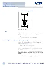
1. Series KRG is stationary:

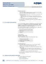
KRG

direction of
movement

load

Fig. 3: Series KRG stationary

Operating Manual

Safety Locks series KRGP

Pneumatic / compressive load

Original instructions BA-S12-en-1-15

© SITEMA GmbH & Co. KG . G.-Braun-Straße 13 . 76187 Karlsruhe (Germany) . Phone: +49(0)721/98661-0 . Fax: -11 . www.sitema.com

11/28

Содержание KRGP Series

Страница 1: ... instructions BA S12 en 1 15 SITEMA GmbH Co KG G Braun Straße 13 76187 Karlsruhe Germany Phone 49 0 721 98661 0 Fax 11 www sitema com 1 28 Operating Manual BA S12 Safety Locks series KRGP þ high holding forces through self reinforcing clamping þ for static loads þ compact design ...

Страница 2: ... Storage 14 6 Preconditions for use 14 6 1 Location requirements 14 6 2 Requirements for the clamping rod 15 7 Installation 16 7 1 Feeding in clamping rod 16 7 2 Attach Safety Lock 17 7 3 Making pressure connection 18 7 4 Checking port T 19 7 5 Connect proximity switch optional equipment in special designs 20 7 6 Checking installation 20 8 Performance test 20 8 1 Testing holding force 21 8 2 Testi...

Страница 3: ...Disassembly 27 13 2 Disposal 28 14 Technical data sheet 28 Operating Manual Safety Locks series KRGP Pneumatic compressive load Original instructions BA S12 en 1 15 SITEMA GmbH Co KG G Braun Straße 13 76187 Karlsruhe Germany Phone 49 0 721 98661 0 Fax 11 www sitema com 3 28 ...

Страница 4: ...tment instructions for proximity switch holders a dimensional drawing where appropriate for modified standard designs supplementary information for included proximity switches proximity switch data sheet Be sure to comply with the instructions and notices contained in those docu ments 1 3 Explanation of symbols Safety notices in this manual are flagged by symbols Safety notices start with a signal...

Страница 5: ...ovides an overview of all key safety aspects for the protection of personnel and to ensure safe trouble free operation The sections covering the individual life phases contain additional task specific safety notices 2 1 Intended use The Safety Lock holds static loads Use in accordance with the intended purpose also means complying with all the stipulations set out in this manual and in the associa...

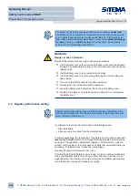
Страница 6: ...ty Lock 2 2 Regular performance testing Regular performance testing ensures safe functioning of the Safety Lock Use the performance test to verify safe functioning of the Safety Lock also after unforeseen events occur A performance test must be carried out in the following cases after installation after any use at variance from the intended use In safety applications the functioning of the Safety ...

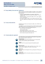
Страница 7: ... potential hazards take necessary measures to eliminate hazards apply accepted technical standards rules and directives carry out necessary repair and assembly work 2 5 Personal protective equipment Personal protective equipment preserves the health and safety of personnel when carrying out their work Use the personal protective equipment stipu lated in the various sections of this manual Industri...

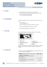
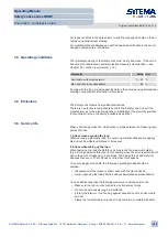
Страница 8: ...sible load 2 Product designation 7 Operating pressure min max 3 Type e g KRG 45 KRGP 22 8 Year of manufacture 4 ID number 9 Weight 5 Serial number 10 CE marking Make sure the name plate is not damaged removed or rendered unreadable Quote the data on the name plate when submitting technical queries to SITEMA 3 2 Pressure fluid The following data apply to standard designs Other pressure fluids may o...

Страница 9: ...ess 1 Stress when securing the load When securing a stationary load the occurring material stresses are negligi ble and can be withstood millions of times over 2 Stress when taking up the load When taking up the load the Safety Lock may reach the maximum holding force During operation this occurs for example when the drive is switched off and in the event of leakage or a line break The design forc...

Страница 10: ...ning with wiper 7 Housing 8 Free face side with threads for attached components Optional equipment in special designs Proximity switches not supplied in scope of delivery available as options The ports are identified by steel punch numbers and letters The positions of the ports may vary depending on the design 4 2 Function The Safety Lock holds static loads Secure load operating state There is a c...

Страница 11: ...e component moving with the load If the Safety Lock is integrated into the machine as a stationary compo nent the load e g the slide is normally movable If the Safety Lock moves with the load e g with the slide the rod is nor mally stationary To avoid constraint forces on the rod attach either the Safety Lock or the rod loosely radially floating When configuring the layout pay attention to the loa...

Страница 12: ...t the following sig nals to the machine controller proximity switch in holder 1 load secured proximity switch in holder 2 clamping released When proximity switch 1 signals load secured and there is no more residual pressure at port L the load is secured The signal is used to allow access to the danger zone When proximity switch 2 signals clamping released movement is allowed in both directions The...

Страница 13: ...andling attachments such as ropes and straps only at rounded edges and corners Do not knot or twist the handling attachments Ü Place the load down when leaving the workplace 5 2 Packaging To protect against dirt contamination corrosion and other damage the Safety Lock is packed in plastic sheeting Leave the sheeting on until just before in stalling the unit Dispose of the sheeting appropriately 5 ...

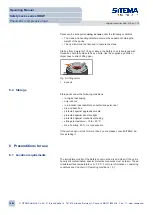
Страница 14: ...against aggressive media protected against direct sunlight protected against mechanical shaking storage temperature 10 to 60 C max humidity 60 no condensation If the unit is kept in stock for more than 2 years please consult SITEMA be fore installing it 6 Preconditions for use 6 1 Location requirements The immediate vicinity of the Safety Lock must be dry and clean If the unit is heavily dirt cont...

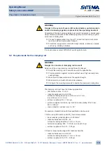
Страница 15: ...trength Ü Make sure the rod will not bend under pressure Ü Configure the mounting elements to handle the maximum holding force The clamping rod must have the following properties ISO tolerance zone f7 or h6 induction hardened min HRC 56 surface hardening depth up to ø 30 mm min 1 mm ø over 30 mm min 1 5 mm surface roughness Rz 1 to 4 μm protection against corrosion e g hard chromium plating 20 10 ...

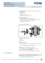
Страница 16: ...ions against unintentionally being turned on Ü Secure moving machine parts against dropping while carrying out work procedures Ü Leave the Safety Lock assembled Do not open the Safety Lock Ü Secure all moving parts especially the rod and Safety Lock separately so that they do not drop down or topple over Ü Make sure mounting screws have the required tightening torques 7 1 Feeding in clamping rod B...

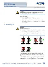
Страница 17: ...njury and damage to assets Ü Secure the Safety Lock and clamping rod separately Ü Secure the Safety Lock and clamping rod by suitable means before and during mounting If the rod is rigidly attached mount the Safety Lock with a radially loose spring base You can find SITEMA spring bases in Technical data sheet TI B20 If the rod is loosely attached such as by suspension of the rod as a radial loose ...

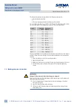
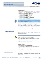
Страница 18: ...r 1 Move the Safety Lock to the mounting position 2 Align the Safety Lock 3 Make sure there are no constraint forces occurring transverse to the rod 4 Fix the Safety Lock to the machine part with the required tightening torque 7 3 Making pressure connection WARNING Danger if the pressure fluid discharge is slowed Slowing of the pressure fluid discharge might cause danger as the clamp will then onl...

Страница 19: ...ssure port from L 2 Connect the stationary compressed air supply to L If tapping is heard while pressure is being is applied Fit a throttle 1 in the p line upstream of the switching valve If the pressure is able to fall below the minimum Fit a check valve 2 in the p line upstream of the switching valve 7 4 Checking port T Internal changes in volume during switching are equalized via port T For thi...

Страница 20: ...ck the electrical connection to the proximity switches 5 Before putting the unit into service carry out a performance test see Chapter 8 Performance test 20 8 Performance test Regular performance testing ensures safe functioning of the Safety Lock Use the performance test to verify safe functioning of the Safety Lock also after unforeseen events occur The performance test consists of the following...

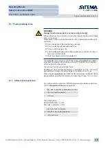
Страница 21: ...urpose The rod must not slip under this test force Depending on type the tapering distance is a maximum of 2 mm This drop is admissible as a relative movement between the Safety Lock and rod When using a spring base the stroke h of the spring base is added to this ta pering distance resulting in a total drop depending on type of 7 to 8 mm 8 1 1 Safety related application For a safety related appli...

Страница 22: ...chine Max load in operation admissible load M Safety margin Test force Practical example Admissible load M 12 kN Max load in operation 10 kN Customer specific safety margin 30 maximum load 3 kN 10 kN max load in operation 3 kN 30 max load in operation 13 kN test force Follow this procedure 1 Secure the maximum load that can occur during operation with the Safety Lock see Chapter 9 2 Securing the l...

Страница 23: ...f malfunctions occur contact SITEMA We will be glad to help 9 Putting into service This chapter sets out instructions on how to activate and set the various oper ating states of the Safety Lock WARNING Danger if the unit is put into service improperly Improper initial putting into service might result in serious injury and major damage to assets Ü Make sure all installation work has been completed...

Страница 24: ...llow this procedure 1 Stop the rod completely 2 Disconnect the pressure from pressure port L ð The clamp closes ð The load has been secured ð Proximity switch 1 signals load secured 9 3 Taking up the load Pressure port L is depressurized The holding force is built up only when the load continues moving in the direction in which it is to be secured Apply the load to the Safety Lock such as by relea...

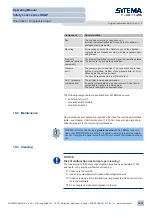
Страница 25: ...ters for port T proximity switch holders proximity switches 10 2 Maintenance No maintenance procedures are required other than the routine performance tests see Chapter 8 Performance test 20 Do not apply high viscosity lu bricants grease to the rod during maintenance SITEMA recommends having a general overhaul of the Safety Lock car ried out at SITEMA s factory after 5 6 years in service preventiv...

Страница 26: ... bar pressure and despite mm upward movement irregular dropping rod slipping under kN load leakage from response time ms too long 12 Repairs The Safety Lock is a safety component Repairs may only be carried out by SITEMA If unauthorized repairs are carried out there is a resultant risk of in jury and of malfunction SITEMA accepts no responsibility for this 13 Disassembly and disposal Personnel saf...

Страница 27: ...into the local plant the Safety Lock might be disassembled separately from the clamping rod or only together with it The following describes both cases Combined disassembly of clamping rod and Safety Lock Follow this procedure 1 Discharge accumulated residual pressures 2 Disconnect the complete pressure supply from the Safety Lock 3 Secure the Safety Lock and clamping rod separately 4 Loosen the m...

Страница 28: ... the Safety Lock The only elec tronic components are the externally mounted proximity switches optional equipment Follow this procedure 1 Remove the proximity switches and dispose of them in accordance with environmental regulations 2 Scrap the Safety Lock in its entirety 14 Technical data sheet The data is accurate at the time of printing this manual The latest version is available at www sitema ...

Отзывы: