4 Design and function
KRG-series Safety Locks are pressure versions. When a load is applied, it
pushes the Safety Lock onto the machine component. The load is transmitted
into the machine via the mounting surface of the Safety Lock.
Attention must be paid to how the load acts on the rod and to the Safety Lock
particularly when configuring the layout. For more information see chapter
Layout
.
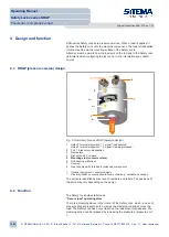
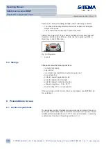
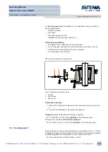
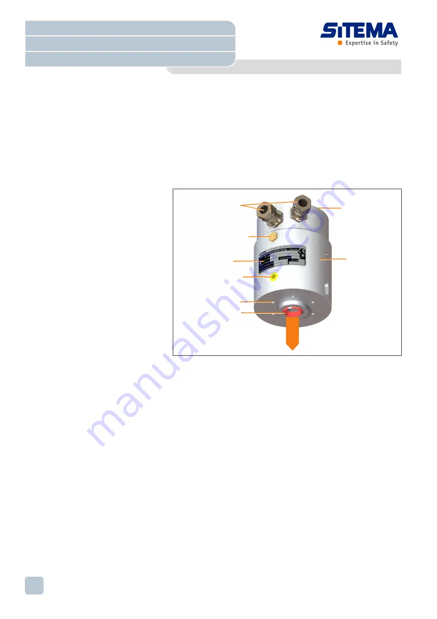
4.1 KRGP (pressure version) design
2
1
3
4
5
6
7
8
load
Fig. 2: Overview of series KRGP (example design)
1
Holder* for proximity switch** 1, signal “load secured”
Holder* for proximity switch** 2, signal “clamping released”
2
Port T “pressure compensation”
3
Name plate
4
Pressure port L “release”
5
Mounting side (contact surface)
6
Rod opening with wiper
7
Housing
8
Free face side with threads for attached components
*
Optional equipment in special designs
**
Proximity switches not supplied in scope of delivery; available as options
The ports are identified by steel punch numbers and letters. The positions of
the ports may vary depending on the design.
4.2 Function
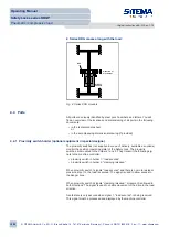
The Safety Lock holds static loads.
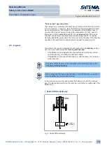
“Secure load” operating state
There is a clamping sleeve in the interior of the Safety Lock, which, in case of
pressure drop at pressure port L, clamps the clamping rod and secures the
load. The Safety Lock has not yet taken up the load when this happens. The
clamping action can be released by increasing the pressure at pressure port
L.
Operating Manual
Safety Locks series KRGP
Pneumatic / compressive load
Original instructions BA-S12-en-1-15
© SITEMA GmbH & Co. KG . G.-Braun-Straße 13 . 76187 Karlsruhe (Germany) . Phone: +49(0)721/98661-0 . Fax: -11 . www.sitema.com
10/28


