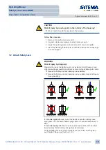
If a
fast response time
of the Safety Lock is stipulated, comply with the fol-
lowing requirements:
• suitable controller
• short lines
• fast valve response times
• installation of a dump valve directly on L
Check the preconditions:
• The Safety Lock is attached to the machine part.
• The rod has been inserted. No constraint forces are acting on the rod.
• A temporary pressure supply has been connected.
• The connection lines are clean.
The pressure supply is connected to L.
p
p
1
2
3
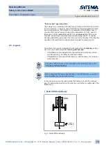
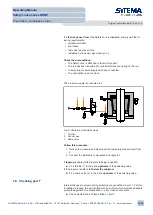
Fig. 6: Actuation (schematic view)
1
Throttle
2
Check valve
3
Dump valve
Follow this procedure:
1. Relieve the pressure and disconnect the temporary pressure port from
L.
2. Connect the stationary compressed air supply to L.
If
tapping
is heard while pressure is being is applied:
► Fit a throttle (1) in the p line
upstream
of the switching valve.
If the pressure is able to fall
below the minimum
:
► Fit a check valve (2) in the p line
upstream
of the switching valve.
7.4 Checking port T
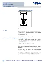
Internal changes in volume during switching are equalized via port T. For this
“breathing” process, the port is fitted with an air filter which provides adequate
protection against dirt contamination in a dry, clean environment.
► Check whether the air filter is fitted on port T.
Operating Manual
Safety Locks series KRGP
Pneumatic / compressive load
Original instructions BA-S12-en-1-15
© SITEMA GmbH & Co. KG . G.-Braun-Straße 13 . 76187 Karlsruhe (Germany) . Phone: +49(0)721/98661-0 . Fax: -11 . www.sitema.com
19/28

