


1
2
3
213--- 2
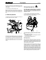
1
2
3
4
5
6
7
8
9
10
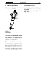
8
7
6b
6a
5
4
3
2
1
Fuel System
13---3
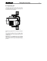
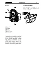
Bosch---P injection pump
1. Boost control
2. Cold start solenoid
3. Speed lever
4. Injection timing indicator
5. Lube oil into the injection pump
6. Hand pump
7. O---ring seal
8. Return of lube oil to engine
9. Identification plate
10. Overflow valve
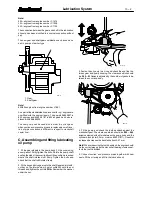
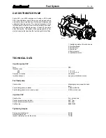
Bosch---A injection pump
The injection pump is an in---line pump and the basic con-
struction is the same in all engines irrespective of the cylinder
number. The fuel injection pump is flange mounted and
sealed by one o---ring in the timing gear casing. The injection
pump is driven from the crankshaft through an idler gear. The
injection pump is connected to the engine force---feed lu-
brication system through an external pipe. Lubricating oil re-
turns to the engine via the hole at the front end of the injection
pump. In some versions, specially locally installed engines,
the return of the oil is lead through a hose from the regulator
cover to the crankcase.
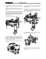
The fuel feed pressure which fills the high pressure pump el-
ements with fuel is created by a piston pump which is at-
tached to the side of the fuel injection pump. The piston pump
is driven from an eccentric on the camshaft of the injection
pump. The fuel feed pump supplies more fuel than the injec-
tion pump needs. The excess fuel flows through the overflow
valve back to the fuel tank. The fuel cools the injection pump
and also takes any air bubbles with it back to the tank.
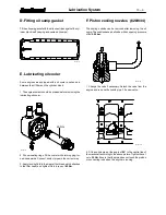
1. Oil filler plug
2. Speed lever
3. Hand pump
4. Lube oil into the injection pump
5. O---ring seal
6a. Return of lube oil to engine
6b. Alternative oil return to engine
(e.g. aggregate application)
7. Drive gear
8. Identification plate
Injection pump with the boost control
1. Boost control
2. Cold start solenoid
3. Indicator plug for adjusting injection timing


