


Timing Gear Assembly
9---1
9. TIMING GEAR ASSEMBLY
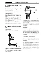
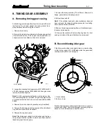
A. Removing timing gear casing
As the timing gear casing bottom face forms a part of the mat-
ing face for the oil sump gasket, the casing cannot be re-
moved without first removing the oil sump.
1. Remove the oil sump.
2. Remove the radiator, fan, alternator, belt tensioning and belt
(if not removed earlier). If the engine is equipped with a air
compressor or air conditioner, it has to be removed.
9101 65700
29--- 1
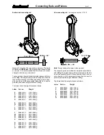
3. Loosen the crankshaft nut (special tool 9101 65700 for 320,
420, 620---engines and tool 9024 55800 for 634 engines) and
remove the belt pulley/hub.
Note!
On 620---engines the belt pulley must be removed be-
fore unscrewing the nut. If the 620---engine is equipped with
a viscose damper, the front end nut is opened with tool 9024
55800.
4. Remove the drive unit and hydraulic pump (if installed).
5. Remove the timing gear casing cover and the oil deflector
ring at the front end of the crankshaft.
6. Remove the injection pump.
Note!
If the timing gear casing is not to be changed, the injec-
tion pump can remain in place. In which case disconnect all
leads and pipes from the pump.
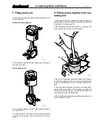
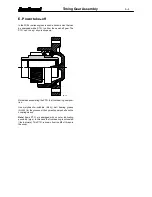
7. Unscrew the idler gear bolts (17 and 22 mm). Remove the
flange, gear wheel and bearing journal.
8. Extract the camshaft.
Note!
If the cylinder head and valve mechanism have not
been removed, the tappets must be prevented from falling
down, see instruction point
4 B
.
9. Remove the timing gear casing. Ensure that all sealing sur-
faces are not damaged.
10. Remove the crankshaft front sealing ring from the front
casing and clean all the parts that have been removed.
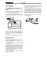
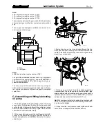
B. Reconditioning idler gear
If the idler gear bushing is changed, press in a new bushing
so that its rear edge is
0,1...0,25 mm
inside the gear wheel
rear edge (see picture on next page).
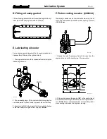
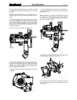
1
2
29--- 2
1. Chuck of lathe
2. Roller ø=5 mm
Machine the idler gear bushing inner diameter to a correct di-
mension after fitting. Centre the idler gear according to figure
above so that tooth backlash is kept the same.


