


95
8317
8317
N/B Maintenance
N/B Maintenance
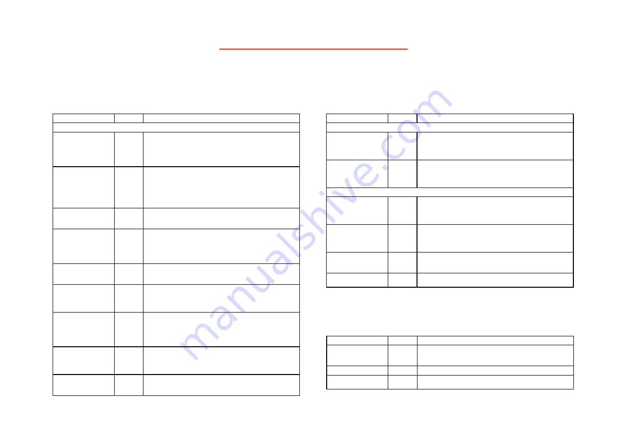
5.3 ULI M1573 South Bridge(2)
LAN Interface
Pin Name
I/O Type Description
MII Interface
MII_COL I
Collision Detect.
Asserted high to indicate detection of collision conditions in
10Mbps and 100Mbps Half Duplex modes. In Full Duplex
mode, this signal is always logic 0. There is no heartbeat
function in Full-Duplex mode.
MII_CRS I
Carrier Sense.
This pin is asserted high to indicate the presence of carrier due
to receive or transmit activities in 10BASE-T or 100BASE-TX
Half Duplex modes.
In Repeater, when Full Duplex or Loopback mode is a logic 1, it
indicates the presence of carrier due only to receive activity.
MII_RXER I
Receiver Error.
Receiver error asserts when a data decoding error is detected by
the external PHY device.
MII_RXC I
Receive Clock.
Provides the recovered receive clock for different modes of
operation:
- 25MHz nibble clock in 100Mbps mode
- 2.5MHz nibble clock in 10Mbps nibble mode
MII_RXD[3:0] I
Receive Data.
Nibble wide receive data (synchronous to RX_CLK – 25MHz
for 100BASETX mode, 2.5MHz for 10BASE-T nibble mode).
MII_RXDV I
Receive Data Valid.
Data valid is asserted by the external PHY device when receive
data is present on the RXD lines and is de-asserted at the end of
packet.
MII_TXC I
Transmit Clock.
Transmit clock input from the PHY.
- 25MHz nibble transmit clock derived from transmit Phase
Locked Loop(TX PLL) in 100BASE-TX mode
- 2.5MHz transmit clock in 10BASE-T nibble mode
MII_TXD[3:0] O
Transmit Data.
Transmit data output pins for nibble data from the MII in
100Mbps or 10Mbps nibble mode (25 MHz for 100Mbps mode,
2.5MHz for 10Mbps nibble mode).
MII_TXEN O
Transmit Enable.
Active high output indicates the presence of valid nibble data on
TXD[3:0] for both 100Mbps or 10Mbps nibble mode.
LAN Interface (Continued)
Pin Name
I/O Type Description
MII Interface
MII_MDC O
Management Data Clock.
Synchronous clock to the MDIO management data input/output
serial interface which is asynchronous to transmit and receive
clocks. The maximum clock rate is 2.5MHz.
MII_MDIO I/O
Management Data I/O.
Bi-directional management instruction/data signal that may be
sourced by the station management entity or the PHY. This pin
requires a 4.7Kohm pull-up resistor.
EEPROM Interface
EEDO O
Serial EEPROM data output
It is connected to DI( data input ) pin of the serial EEPROM and
used to transfer the data from the south bridge to the EEPROM.
The Serial ROM is used to auto-load Ethernet GUID.
EEDI I
Serial EEPROM data input
It is connected to DO( data output ) pin of the serial EEPROM
and used to transfer the data from the EEPROM to south bridge.
The Serial ROM is used to auto-load Ethernet GUID.
EECS O
EEPROM Chip Select.
This pin will enable the EEPROM during loading of the
Configuration Data.
EECK O
EEPROM Serial Clock.
This pin provides the clock for the EEPROM data transfer.
SMBus Interface
Pin Name
I/O Type Description
SMB_ALERT#/
RSMGPI[10]
I
SMBus Alert SMBus devices can signal alert to SMBus host by
asserting this signal to generate SMI or to wake up the system.
This pin can be configured as RSMGPI.
SMB_CLK
I/OD
SMBus Clock SMBus clock signal driven by cycle initiator.
SMB_DATA
I/OD
SMBus Data SMBus data signal carries serial data information
based on SMCLK.


