Sintrol Dumo Series Скачать руководство пользователя страница 72


©2021 Sintrol. 

All rights reserved. 


72 (104) 


Revision 4 


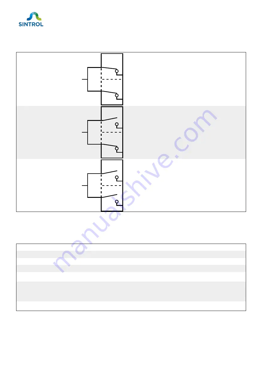
Table 16: Relay statuses 

Relay status 

Relay contacts 

Description 

Relay 1: Energized 

Relay 2: Energized 


The device operates normally, and dust 

concentration is below the configured ALERT 

and ALARM thresholds. 


Voltage is supplied to both relays. 

Relay 1: Relaxed 

Relay 2: Energized 


The dust concentration is above the ALERT 

threshold but below the ALARM threshold. 


Relay 1 switches status and triggers ALERT. 

Voltage is supplied to Relay 2. 

Relay 1: Relaxed 

Relay 2: Relaxed 


The dust concentration is above the configured 

ALARM threshold. 


Relay 2 switches status and triggers ALARM. 

Both relays are relaxed. 


The operation logic of the relays is described in Table 17. 

Table 17: Operation logic of the relays 

Device status 

Relay 1 status 

Relay 2 status 

Analog signal (mA) 

NORMAL OPERATION 

Energized 

Energized 

According to dust level 

ALERT 

Relaxed 

Energized 

According to dust level 

ALARM 

Relaxed 

Relaxed 

According to dust level 

MAINTENANCE 

Energized 

Relaxed 

According to dust level 

AUTO SETUP 

Energized 

Relaxed 

>22 mA 

ZERO/SPAN CHECK 

Energized 

Relaxed 

4 mA for Zero check, 

approx. 16.8 mA for 

Span check 

FAULT 

Relaxed 

Relaxed 

>22 mA 


9.2.3


LED and display logic 

The main interface of the device is equipped with a 7-segment display and red and green status LEDs. 

The LEDs are mirrored, and their function is the same regardless of their location on the main interface. 

C

1

2

C

1

2

C

1

2

Содержание Dumo Series

Страница 1: ...USER MANUAL Dumo Series Ambient Dust Monitor Model DumoPro...

Страница 2: ...se whether or not seller knows or has reason to know has been advised or is otherwise in fact aware of any such purpose whether alleged to arise by law by reason of custom or usage in the trade or by...

Страница 3: ...easurement results 21 4 Storage 24 5 Mechanical installation 25 5 1 Unpacking and inspection 25 5 1 1 Unpacking 25 5 1 2 Inspection 25 5 2 Selecting installation location 25 5 2 1 Ambient environment...

Страница 4: ...old 78 9 4 7 Parameter 6 Alarm delay time 79 9 4 8 Parameter 9 Zero Span check interval 79 9 4 9 Parameter 10 Command parameter 79 9 4 10 Parameters 11 to 14 Displaying measurement results in mg m3 81...

Страница 5: ...request a new copy from the manufacturer or an authorized distributor 1 1 Description of symbols These symbols are used to alert you to any potential personal injury hazards and to provide informatio...

Страница 6: ...hat are marked with this symbol must not be disposed of with general waste If a defective or broken down device cannot be repaired it must be recycled and disposed of in accordance with WEEE directive...

Страница 7: ...the intended use of the device that are not described in this manual contact the manufacturer or an authorized distributor In addition to the safety instructions described in this manual the personnel...

Страница 8: ...d the manufacturer cannot guarantee safe operation of the device Before installing and commissioning the device carefully inspect it for any damage or defects Do not use the device if it is damaged or...

Страница 9: ...Do not use the device in potentially explosive atmospheres An ATEX certified model of the device is available Only ATEX certified models can be used in potentially explosive atmospheres If you have or...

Страница 10: ...ts from dust particles If the measured airflow contains liquid droplets the measurement results are inaccurate The device has a local user interface with six keys and a 7 segment display with four dig...

Страница 11: ...7 segment display with four digits Additionally you can connect the device to a computer using USB RS 485 bus or an optional radio frequency RF communication and change the parameters using complemen...

Страница 12: ...ion 4 Figure 2 Front view of the dust monitor Bolt hex 4 mm Status LEDs magnetic switches Front plate 7 segment display Bolt hex 5 mm Figure 3 Rear view of the dust monitor Bolt hex 4 mm Bolt hex 5 mm...

Страница 13: ...4 Electrical connections on the main board Mode selector key Solid state relay terminal AUTOSETUP key RS 485 bus RS 485 terminator switch Analog mA output Navigation keys Ground connection 24 V DC po...

Страница 14: ...ension drawings Dust monitor side view Figure 5 Side view dimensions of the enclosure Dust monitor front view Figure 6 Front view dimensions of the enclosure 290 00 mm 11 42 in 265 00 mm 10 43 in 313...

Страница 15: ...acket dimensions Mounting bracket is attached to the device using the 5mm hex bolts on the outer edge of the device enclosure This enabled the device to be installed in various orientations 60 00 mm 2...

Страница 16: ...ting arm dimensions 3 2 2 Identification Identification label is located on the bottom of the device Figure 10 Identification label Manufacturer details Serial number Approvals IP rating Device model...

Страница 17: ...n and red LEDs for status indication Auto Setup function for easy commissioning Mode selector key with user selectable FAST MEDIUM and SLOW response modes Two independent solid state relays to indicat...

Страница 18: ...ce can be customized to meet the specific requirements for various applications and process conditions Mounting bracket The device can be installed in multiple angles and orientations with an optional...

Страница 19: ...that can also be rotated around their center axis The device enclosure has built in holes on the bottom side where the mounting arm can be attached in 90 steps Probe coating The sensor probe can be eq...

Страница 20: ...r setting up wireless device networks Part number PC900090 DustLog 10 reporting software for additional data logging and reporting options 3 5 Operating principle The device is designed for continuous...

Страница 21: ...the IEU value and mA output signal is established automatically with the Auto Setup function It is also possible to display the measurement results in mg m3 However in this case the IEU value and outp...

Страница 22: ...dusts generate extremely low signals For measuring such dusts the device must be tested with a dust sample before delivery Common dust particle materials include Grains Sugar Coal Cosmetics Dyes Cera...

Страница 23: ...ice monitors the fan performance to ensure that the flow velocity remains stable If the surrounding airflow at the installation location is 5 m s it can affect the internal flow velocity of the device...

Страница 24: ...e the device in its original packaging Do not place any heavy objects on the device Storage temperature must be within range 40 60 C 40 140 F Retain the original packaging in case the device is ever t...

Страница 25: ...at the device and all its standard and optional parts are included in the delivery Inspect the device and its individual parts for any defects or damage that may have occurred during delivery For inst...

Страница 26: ...with occasional condensation it is recommended to install the device in an upward position with the terminal cover and tip of the internal sensor probe pointing down This helps prevent liquid from ac...

Страница 27: ...lation location in relation to airflow direction where the air current carries the dust particles away from the device Figure 17 Incorrect installation location in relation to airflow direction Figure...

Страница 28: ...concentration MEC even if the device indicates a dust concentration that is below the alarm limits An explosion can result in a serious injury or death If the device is part of an explosion preventing...

Страница 29: ...onents When installing or removing equipment the device or the installation surface can be hot Wear appropriate heat resistant gloves and follow all applicable local and plant specific safety codes be...

Страница 30: ...ts you marked in the previous step Use a drill bit that is suitable for the material that the installation surface is made of and that corresponds to the screw thread you are using NOTICE Do not drill...

Страница 31: ...lation of electrical connections Power down the device when you are making electrical connections when you intend to perform maintenance on it or in the event of malfunction Connect the device to line...

Страница 32: ...o all applicable local safety standards When choosing cables consider the following Use a shielded cable if possible Connect the cable shield to ground on one end only Minimum required conductor size...

Страница 33: ...board Figure 20 Main board and electrical connections of the dust monitor Mode selector key Solid state relay terminal AUTOSETUP key RS 485 bus RS 485 terminator switch Analog mA output Navigation ke...

Страница 34: ...hat is smaller than 0 3 mm2 22 AWG to make electrical connections on the device 6 3 3 Grounding WARNING Risk of injury If the dust monitor is not grounded properly it can display false measurement res...

Страница 35: ...IEU when the process is not running The output signal level changes when you touch the enclosure The displays indicate Err1 with the red status LEDs blinking This means that the sensor probe is ground...

Страница 36: ...supply or that the power supply is disconnected or isolated 2 Turn the device on its side and remove the terminal cover located on the bottom of the device by turning it counterclockwise with a pin wr...

Страница 37: ...lide the cable gland over the incoming ground wire 5 Insert the ground wire through the cable entry 6 Loosen the screw on the ground connection with a screwdriver 7 Place the ground wire under the scr...

Страница 38: ...he cable gland back inside the cable entry and tighten the cap with a wrench Attach the terminal cover by tightening it clockwise with a pin wrench or 1 2 inch ratcheting socket wrench 9 Connect the o...

Страница 39: ...a power supply wear protective glasses protective clothing and insulating rubber gloves The device can be connected to a 24 V DC power supply Note the polarity of the power input Only use NEC Class 2...

Страница 40: ...electric work Pin wrench or 1 2 inch ratcheting socket wrench Slotted head screwdriver M3 Wrench 20 mm 0 7874 in or adjustable Suitable power cable To connect the device to power supply 1 Make sure th...

Страница 41: ...ove the cable gland at the cable entry that is closer to the power supply terminal Loosen the cable gland cap by turning it counterclockwise with a wrench 4 Slide the cable gland over the incoming pow...

Страница 42: ...block and tighten the screws 7 If you do not need to make any other electrical connections Push the cable gland back inside the cable entry and tighten the cap with a wrench Attach the terminal cover...

Страница 43: ...er external loads of up to 30 V DC 1 A Figure 23 Relay connections on the main board Connect the sheath of a shielded cable to ground only on one end Connecting both ends to ground can create a ground...

Страница 44: ...n the bottom of the device by turning it counterclockwise with a pin wrench or 1 2 inch ratcheting socket wrench 3 Remove the cable gland at the cable entry that is closer to the relay terminal Loosen...

Страница 45: ...signal cable to contacts 1 2 and C 7 Connect the other end of each signal cable to the appropriate terminals on the application that you want to control with the relays 8 If you do not need to make a...

Страница 46: ...can be used to read data from the device and to change device parameter The device supports Modbus RTU and proprietary Sintrol Network communication protocols The default communication parameters for...

Страница 47: ...tead of B If you are connecting the device into an existing Modbus RTU automation system or if you are using a third party RS 485 to USB converter or cable read the related user documentation carefull...

Страница 48: ...ted 2 Turn the device on its side and remove the terminal cover located on the bottom of the device by turning it counterclockwise with a pin wrench or 1 2 inch ratcheting socket wrench 3 Remove the c...

Страница 49: ...the RS 485 bus you must adjust the settings for each device in DustTool according to instructions in section Wired device network in chapter Commissioning and system setup 7 Connect the other end of...

Страница 50: ...ce is connected to the RS 485 bus switch the terminator switch to ON position First or middle in chain If the device is the first of a chain or in the middle of a chain make sure that the terminator s...

Страница 51: ...on the main board Connect the sheath of a shielded cable to ground only on one end Connecting both ends to ground can create a ground loop To connect the mA output you need Protective gear for electr...

Страница 52: ...the bottom of the device by turning it counterclockwise with a pin wrench or 1 2 inch ratcheting socket wrench 3 Remove the cable gland at the cable entry that is closer to the mA output terminal Loos...

Страница 53: ...ble to mA output terminal block Insert the wires to the terminal block and tighten the screws 7 Connect the other end of the signal cable to the device that receives the mA output 8 If you do not need...

Страница 54: ...ver when using USB power the internal fan of the device does not rotate and the device cannot measure dust concentration This means that USB can only be used to change the parameters and settings of t...

Страница 55: ...k the device with a device specific master password You can download DustTool free of charge at https sintrol com product dusttool DustTool is developed to set up and manage the device parameters and...

Страница 56: ...features related to calibration parameters Auto Setup and commands Monitor view provides a visualization of the current process conditions Info area on the bottom of the window displays information ab...

Страница 57: ...conditions after the device is installed and the process that the device monitors is running Make sure that Auto Setup is performed during normal operating conditions and usual dust levels Performing...

Страница 58: ...sponse mode overwrites any previously made parameter changes For more detailed information about device parameters see section Parameters in chapter Operation 8 1 3 Operation statuses Table 11 shows t...

Страница 59: ...surement range ALERT is triggered when there is a 5 increase in dust level compared to the baseline In the example this corresponds to an output signal of 8 mA and a dust concentration of 50 mg m3 Dus...

Страница 60: ...ng between green and red 2 Press AUTOSETUP key for 1 second During Auto Setup The display shows the remaining time in seconds Both green LEDs continue to blink 3 Auto Setup is completed when the count...

Страница 61: ...th a blinking digit 2 Select the parameter you want to edit The selected parameter is displayed in display position D0 Press K0 key to select the next parameter Value of the selected parameter is disp...

Страница 62: ...RS 485 interface The software automatically detects the interface that is used for communication and connects to the device If multiple devices are connected to the same computer you must select the...

Страница 63: ...Tool For information on how to connect the RS 485 bus see section Connecting RS 485 bus in chapter Electrical installation 8 2 4 Wireless connection If your device is equipped with the optional RF ant...

Страница 64: ...communication and connects to the device If multiple devices are connected to the same computer select the device you want to assign a name to from the list on the left side of the main view When con...

Страница 65: ...ngs for each individual device must be adjusted in DustTool To adjust the device settings in DustTool 1 Connect the device to a computer with USB 2 Launch DustTool and navigate to PROPERTIES tab 3 Adj...

Страница 66: ...in communicates through Modbus RTU protocol the first device in the chain must be connected to a Modbus master device If your device chain communicates through Sintrol Network protocol the first devic...

Страница 67: ...nication This means that RF enabled devices can operate seamlessly within the RS 485 network Establishing wireless communication To establish a wireless connection you need A device equipped with the...

Страница 68: ...bility This device acts as a communication station that converts the physical signal from the other devices to radio frequencies The communication station also converts radio frequencies from the host...

Страница 69: ...normal operation K2 K2 key Saves the active parameter value K1 K1 key Moves the cursor one step to the right K0 K0 key Enters MAINTENANCE mode Increases the value of the selected blinking digit by 1...

Страница 70: ...nctional logic The device has various operation statuses that are indicated to the user with a combination of LEDs two relays and a 7 segment display with four digits 9 2 1 Operation statuses The oper...

Страница 71: ...ally corrected if it is 3 but 10 of the measurement range If the drift is 10 or if the device is unable to correct the drift the device enters FAULT mode The device generates an output signal accordin...

Страница 72: ...triggers ALARM Both relays are relaxed The operation logic of the relays is described in Table 17 Table 17 Operation logic of the relays Device status Relay 1 status Relay 2 status Analog signal mA NO...

Страница 73: ...lay and LEDs are operating normally press K0 and K3 keys at the same time All four displays are activated displaying 8 8 8 8 and status LEDs on each side of the display are illuminated This indicates...

Страница 74: ...seconds ALERT 5 baseline ALARM 20 baseline SLOW 100 seconds 60 seconds ALERT 5 baseline ALARM 20 baseline The baseline of the previous Auto Setup is always stored in the device memory When you change...

Страница 75: ...ated during Auto Setup 4 ALERT threshold of range 000 100 Default 25 8 mA 5 ALARM threshold of range 000 100 Default 100 20 mA 6 Alarm delay time sec 000 180 Default 30 sec 7 Flow velocity compensatio...

Страница 76: ...icates the currently selected measurement unit every 8 seconds by showing it on the display for 2 seconds For parameter value 000 the device displays for parameter value 001 it displays mA and for 002...

Страница 77: ...Table 23 Examples of adjusting the measurement range with parameter 3 Value Description Dust level at 20 mA 050 Halves the measurement range 10 baseline 100 Default value 20 baseline 200 Doubles the...

Страница 78: ...are not linked and must be set independently For example if you double the maximum measurement range the default parameter 4 value is decreased from 025 to 012 25 to 12 of maximum measurement range 9...

Страница 79: ...ractice this only affects the operation of the device in relation to ALARM and ALERT statuses 9 4 8 Parameter 9 Zero Span check interval Zero span check is an automatic self diagnostics procedure Duri...

Страница 80: ...actory settings with command parameter 10 rewrites all parameter values including the ones set with Auto Setup Enable mg m3 calibration To enable displaying the measurement results in mg m3 1 Press K0...

Страница 81: ...a linear regression curve with an equation To determine the parameter values for parameters 11 to 14 you need to know the values for x intercept and slope The values are calculated from the results of...

Страница 82: ...000 Parameter 12 Decimal part of x intercept Parameter 12 is used to set the calibration value for the decimal part of x intercept when the device is calibrated to display measurement results in mg m3...

Страница 83: ...housands Table 36 Parameter 15 and 16 functions No Parameter Description 5 15 IEU units in millions Parameter value represents million IEU units 6 16 IEU units in thousands Parameter value represents...

Страница 84: ...tributor 9 5 1 Resetting RS 485 settings to factory defaults In case you must reset the device RS 485 communication settings to factory defaults you can manually initiate an internal boot check During...

Страница 85: ...r probe in chapter Maintenance and inspection Err2 Zero span check failed Error code Err2 indicates that zero span check has failed This happens when the device is unable to compensate for the drift o...

Страница 86: ...ice display indicate that the parameters for displaying the measurement results are set improperly The correct procedure to fix this depends which unit of measurement you want to display the measureme...

Страница 87: ...without running Auto Setup the displays indicate 3 Make sure that you have commissioned and set up the device according to instructions in chapter Commissioning and system setup 9 5 5 No output signal...

Страница 88: ...r financial loss resulting from improper use Wear protective glasses when working on electrical connections WARNING Risk of burns due to hot components When installing or removing equipment the device...

Страница 89: ...Make sure that the fan is rotating freely Check that the measurement results are within the expected range Weekly Make sure that the device lid cable glands and cables are tightly secured Remove the...

Страница 90: ...Teflon coated probe only use soft cloth to clean it If you use other kinds of cleaning supplies the Teflon coating can break Always handle a Teflon coated probe with care If the dust build up on a Te...

Страница 91: ...the device is not connected to the power supply or that the power supply is disconnected or isolated 2 Loosen the five bolts on the front panel using the hex keys Use the 4 mm hex key for the four sma...

Страница 92: ...e five bolts NOTICE Maximum tightening torque for the bolts is 7 Nm To avoid equipment damage do not secure the bolts tighter than the maximum tightening torque 10 4 Replacing malfunctioning fan The d...

Страница 93: ...r supply or that the power supply is disconnected or isolated 2 Loosen the five bolts on the rear panel using the hex keys Use the 4 mm hex key for the four small bolts located around the fan grating...

Страница 94: ...eserved 94 104 Revision 4 3 Remove the rear panel 4 The fan cable uses a custom connector that is locked into place with a threaded locking ring Disconnect the fan cable by turning it counterclockwise...

Страница 95: ...ove the fan from the enclosure 6 Install a new fan and secure the fan cable by turning it clockwise using needle nose pliers Make sure that the entire fan cable is in the designated groove and that it...

Страница 96: ...the bolts tighter than the maximum tightening torque 10 5 Returns If you need to return a defective device for repair replacement or disposal contact the manufacturer or an authorized distributor Ret...

Страница 97: ...riate recycling container Any non recyclable packaging material must be disposed of with general waste 11 2 Device Electronic devices that are marked with this symbol must not be disposed of with gene...

Страница 98: ...Power supply requirements 24 V DC 10 Power consumption Up to 10 W Output signals 2 Independent solid state relays max 30 V DC 1 A Isolated active 4 20 mA output loop max loop resistance 250 Communicat...

Страница 99: ...3 dBm user adjustable Receiver sensitivity 110 dBm Communication protocol Proprietary Sintrol Network protocol Typical communication range non line of sight 868 MHz version Up to 1000 m 3280 ft in urb...

Страница 100: ...2021 Sintrol All rights reserved 100 104 Revision 4 Appendix A ISO 9001 certificate...

Страница 101: ...itions available from the manufacturer on request Default Modbus communication parameters Baud rate 38400 Data bits 8 Stop bits 2 Parity None Supported function codes Input registers R Read only 4 Rea...

Страница 102: ...5 mg m3 Calibrated measurement data mg m3 LSB 9 R Last 16 bits of a 32 bit integer Auto Setup remaining time 34 R 16 bit unsigned integer Remaining Auto Setup time in seconds Alarm status 50 R 16 bit...

Страница 103: ...2021 Sintrol All rights reserved 103 104 Revision 4 Notes...

Страница 104: ...ua sintrol com INDIA Representative Office A 2 78 Safdarjung Enclave 110029 New Delhi India Tel 91 9811676061 india sintrol com CHINA Representative Office Room 517 Mingliuweilai Building No 18 Jiaom...

Отзывы: