background image

4

Chapter II System Parameter Setting

Based on grating rule installation and actual needs, set various

parameters to achieve the goal of normal operation.

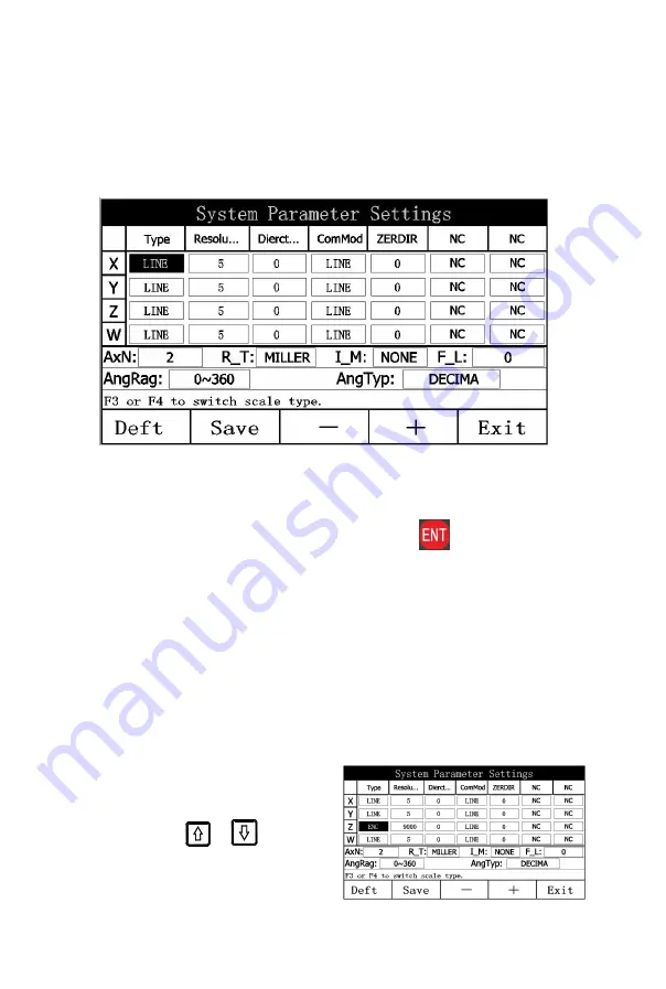
(Figure 2.1)

2.1 Enter/Quit System Parameter Setting

In the time frame of startup screen, Press the

key to enter the

interface of system parameter setting, as shown in Figure 2.1.

After parameter setting, press the “Save” function key to save system

parameter setting and the “Exit” key to quit the interface of system

parameter setting.

2.2 Setting the Number Axis Type

Each axis of the display can be connected with a grating rule to show

the distance or a rotary encoder to show the angle.

Factory default: A grating ruler is mounted.

For example: Set axis Z to mount a rotary encoder.

1) On the interface of system

parameter setting,

Press the

or

key until

the cursor moves to

the type option field for axis Z.

Содержание SDS 2-3VA

Страница 1: ...LCD DIGITAL DISPLAY SDS 2 3VA OPERATION MANUAL...

Страница 2: ...ury directly which must be avoided Warning The prompt of a dangerous case leading to death or serious injury which must be avoided Caution The prompt of a dangerous case possibly leading to death or s...

Страница 3: ...r has its surface damaged the test data would be wrong Users must be especially careful Do not try to repair of remodel the display unit which would otherwise leads to failure malfunction or injury If...

Страница 4: ...ing the Display of Dithering Elimination 9 2 11 Setting the Angle Display Type 10 2 12 Setting the Angle Display Range 11 2 13 Setting the Number Setting Direction for the ZER Coordinate System 11 Cha...

Страница 5: ...Simple arc processing 34 5 5 The Function of measure for taper 39 5 6 200 tool storeroom 33 Chapter VI Calculator Function 42 6 1 Interface introduction 42 6 2 Calculation examples 43 6 3 Calculation...

Страница 6: ...1...

Страница 7: ...Calculator zeroing key Circle holing key for equally divided hole pocessing on an arc Oblique line holing key for equally divided hole pocessing on an oblique line Arc processing key for processing t...

Страница 8: ...signal 6 A 7 5 V 8 B 9 R 2 9 core EIA 422 A signal interface 1 A 2 0V 3 B 4 Wrong signal 5 R 6 A 7 5 V 8 B 9 R 3 EDM signal interface 1 4 5 7 8 9 Null 2 Common 3 Normally off 6 Normally off 4 6 core...

Страница 9: ...2 1 After parameter setting press the Save function key to save system parameter setting and the Exit key to quit the interface of system parameter setting 2 2 Setting the Number Axis Type Each axis o...

Страница 10: ...00 lines For example The resolution on axis Z is set to 180 000 lines 1 On the interface of system parameter setting Press the or key until the cursor moves to To the resolution option field for axis...

Страница 11: ...ounting Direction After the user mounts the grating ruler or encoder actual counting direction may be just opposite to what the user expects This user need can be met in system parameter setting The c...

Страница 12: ...which otherwise would affect measurement accuracy Error correction has two setting types 1 Linear compensation 2 non linear compensation For example Set the compensation mode on axis X to non linear...

Страница 13: ...lay is capable of switching the meter type based on the type of used machine tool After meter type switching the corresponding processing function of the display changes accordingly Factory default mi...

Страница 14: ...ode to Y Y Z 1 On the interface of system parameter setting Press the or key until the cursor moves to to the option field of combination 2 Press the or function key to switch the combination mode to...

Страница 15: ...types degree and degree minute and second After the angle type is switched the display mode of each angle axis is based on this parameter Factory default decimal system For example Set the angle type...

Страница 16: ...he option field of angle range 2 Press the or function key to switch the angle range to 180 180 3 Press the Save function key to save the modification 4 Press the Exit function key to quit the interfa...

Страница 17: ...he Exit function key to quit the interface of system parameter setting Note The number setting direction of the ZER coordinate system must be in accordance with the type of each axis Therefore you nee...

Страница 18: ...ot have to set parameters again 3 2 Zeroing Function Introduction When the display is in normal display state press the number axis zeroing key at any point to zero the displayed value on the coordina...

Страница 19: ...ZER number setting direction is set to 1 the displayed value is equal to the opposite number of the entered value You can set the ZER number setting direction in System Parameter Setting 3 4 Metric B...

Страница 20: ...uction 1 Move the tool and aim it at point A and press the X0 and Y0 keys to zero the count values on both axis X and axis Y 2 Move the tool and aim it at point B 3 Press the 1 2 function keys on both...

Страница 21: ...itched only in normal display state Press the A I function key to switch between ALE and INC The coordinate system prompt bar displays INC in INC state The coordinate system prompt bar displays ALE in...

Страница 22: ...er Setting Based on user needs set related parameters to achieve the goal of proper operation 3 8 1 Setting the LCD Brightness The user can adjust the brightness of the display based on field environm...

Страница 23: ...uit the interface of system parameter setting 3 8 3 Setting the Buzzer Prompt The operator can enable or disable the buzzer prompt tone as required After enabled the buzzer prompt tone sounds with key...

Страница 24: ...19 Note If the modification of system parameter setting is in confusion you can use the Defaults DEFT function key to restore to factory defaults...

Страница 25: ...the ZER zero position changes along for an according distance During work piece processing one benchmark zero position is often not enough to meet user needs but currently added ZER coordinate system...

Страница 26: ...e coordinate system If you enter the relative zero position at a point outside of the absolute coordinate system the position of this point in this user coordinate is displayed If you enter the auxili...

Страница 27: ...ordinate system 4 2 Zero Clearing in Place 1 Move the tool to the absolute coordinate 2 In the absolute coordinate system ALE as shown in Figure 3 1 move the tool to point 0 press keys X0 and Y0 for z...

Страница 28: ...ing efficiency is improved Attention When the user coordinate is used zero clearing in corresponding user coordinate system is actually resetting the auxiliary zero position The position at which zero...

Страница 29: ...allel with the operator is X axis and in the horizontal plane the direction vertical to the X axis is Y axis and that vertical to the horizontal plane is Z axis The direction to which the arrow is poi...

Страница 30: ...h 0 000 which is the position of the hole Example For the work piece as shown in the figure the parameters are set as follows Line distance LineLth 45mm Line angle Angle 30 Hole number Pots 4 Operatio...

Страница 31: ...he machine tool to the position where 0 is displayed in both the X window and Y window Punching can be started at that point 7 After processing is completed press to return to the normal display statu...

Страница 32: ...hen processing is required When the direction is set to be 0 it is indicated that the direction from the starting angle to the end angle is the anti clockwise direction as the arc shown in Figure A Th...

Страница 33: ...r the display size unit Move the machine tool Set the origin of coordinates to be at the 0 point 2 Press The interface of the function of making holes along a circle at an equal interval is displayed...

Страница 34: ...ue plane slope processing When an oblique plane of relatively large slant angle is to be processed it is the most easy and simple to use the function of oblique plane processing I Oblique plane calibr...

Страница 35: ...til zero is displayed 6 Adjust the angle of the work piece so that the work piece contact the measurement tool And continue until zero is displayed For example Calibrate the angle of the work piece to...

Страница 36: ...is in the XZ or YZ plane through the function of oblique plane processing the operator is gradually directed to process the oblique plane The steps of the function of oblique plane processing When th...

Страница 37: ...is 5 Input the coordinates of the end point X axis Z axis 6 The interface of Proc is displayed Press or to switch over between the numbers of the processing points Move the machine tool to the positio...

Страница 38: ...ger and the arc to be processed is rougher the processing time is shorter A Processing ZX and YZ planes There are 8 processing methods as shown in the following figure when arcs on ZX and YZ planes ar...

Страница 39: ...s parameter is especially for XY plane processing Example 1 The arc AB of 90 as shown in Figure 4 4 1 is to be processed from point A starting to point B end The parameters are set as follows The plan...

Страница 40: ...Input the cutter diameter Press in sequence Input the cutter diameter 8 Input the max cutting volume Press in sequence Input the max cutting volume 9 Select the inner arc outer arc mode Press Select t...

Страница 41: ...re set as follows The plane to be processed XZ Processing mode 5 Arc radius actual value Cutter diameter actual value round head cutter Max cutting volume to be determined by the user himself herself...

Страница 42: ...n taper and angle 4 Quit Press key 5 6 200 tool storeroom It will need to use different tools when turning different work pieces or different surface of work pieces so it is necessary to uninstall and...

Страница 43: ...oving the lathe platform to make the display of X axis and Y axis become zero 5 The tool storeroom can store datum of 200 tools Notes the Y axis value mentioned above is the integrated value of Y axis...

Страница 44: ...tool Default the first tool as the base tool you can also set the other tool as the base tool key number is OK 3 Call the second tool Move Cursor to call tool Press 4 open the tool Move cursor to tool...

Страница 45: ...sferred to the axis to be processed The user only needs to move the drilling machine to the position at which 0 is displayed which is the calculation results indicate In the normal display status pres...

Страница 46: ...in g 6 2 Calculation examples Example 1 2 30x2 6 2 59 Example 2 345 2 x sin 1 0 5 285 Note In case of a digit input error press CA key to input again In case of any mistake in the calculation process...

Страница 47: ...o that the displayed value is equal to the standard value Note The linear error correction value is set by the installation personnel and must not be modified by the user at will which otherwise would...

Страница 48: ...mm m 1 500 mm m The actually measured length of the machine tool workbench is 1000 while the finally displayed value at the display is 999 98 S 1000 999 98 1000 1000 0 02 mm m After the correction fac...

Страница 49: ...ating ruler L1 The length of the compensation section L2 The effective distance of compensation Note The user can set the preceding distance at will according to the actual requirement There is no req...

Страница 50: ...nsation starts at this point According to Figure 2 directly display the position with 0 000 as the coordinates value Press the axis zero clearing key It is indicated that the compensation starts at th...

Страница 51: ...ded 2 Check the 220V power The displayed value of a certain axis is two times of the normal value 1 The resolution ration of the grating ruler is not correctly set 2 The diameter display mode is set f...

Страница 52: ...ation value of the display is not properly set 7 The grating ruler is damaged thus causing missing number 1 Repair the machine tool 2 Reduce the speed 3 Reinstall the grating ruler 4 Convert mm inch c...

Страница 53: ...V1 0 202110...

Отзывы: