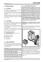
Base current setting indicator (5)
Only available when pulse mode (12) is selected. Sets
the current of the low/ base pulse. Unit(A) and setting
range (5-320A/400A).
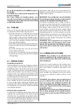
Down slope setting indicator (6)
When the trigger is released, the welding current
will reduce gradually over the time selected down
to 0. This allows the operator to complete the weld
without leaving a ‘crater’ at the end of the weld pool.
Unit(S) and setting range (0-10S).
End current setting indicator (7)
Available in 4T trigger mode, sets a welding current
5-100% of the main welding current activated when
the trigger is held on to ‘unlatch’ the trigger before
the weld is finished. If downslope (6) is set, the cur-
rent will go through the downslope period before
going to the end current set. When the trigger is re-
leased, the arc will stop.
Post gas flow setting indicator (8)
Controls the period of time the shielding gas contin-
ues to flow for after the arc is stopped. This protects
the weld area and torch tungsten from contamina-
tion while it is still hot enough to react with atmo-
spheric gases, after the weld is finished. Unit(S) and
setting range (0-10S).
Pulse width setting indicator (9)
Only available when pulse mode (12) is selected.
Sets the time proportion as a percentage between
the peak current and base current when using pulse
mode. Neutral setting is 50%, the time period of the
peak current and base current pulse is equal. High-
er pulse duty setting will give greater heat input,
while lower pulse duty will have the opposite effect.
Unit(%) and setting range (5-95%).
Pulse frequency setting indicator (10)
Only available when pulse mode (12) is selected. Sets
the rate that the welding output alternates between
the peak and base current settings. Unit(Hz) and set-
ting range (0.5-200Hz).
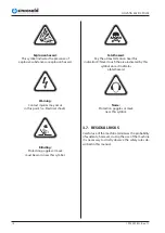
Pulse mode ‘off’ indicator (11)
Pulse mode ‘On’ indicator (12)
Pulse welding
Pulse welding mode switches the welding output
between a high and low current output in a cyclical
manner. When used correctly this function has sub-
stantial benefits in the TIG welding process including
greater weld penetration for less work heat input and
greater control of the weld pool.
The basic theory for setting the base current using
TIG 2T/4T Trigger Control (20)
2T mode the trigger is pulled and held on to activate
the welding circuit, when the trigger is released, the
welding circuit stops. 4T is known as ‘latching’ mode.
The trigger is pulled once and released to activate the
welding circuit, pulled and released again to stops
the welding circuit. This function is useful to longer
welds as the trigger is not required to be held on con-
tinuously. TIG series of welding machines also has
more advanced current controls that can be used in
4T mode.
Parameter Select/ Adjust Knob (22)
Switch between welding parameter settings by
pressing this knob, adjust by turning the knob. Value
of the parameter selected will be shown on the digi-
tal multifunction display (18).
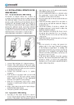
TIG Parameter Setting
4
5
6
3
9
8
1 2
10
7
Pre gas flow setting indicator (1)
Controls the period shielding gas will flow for when
the torch is triggered before the arc starts. This purg-
es the work area of atmospheric gas which could con-
taminate the weld before the weld starts. Unit(S) and
setting range (0-2S).
Start current setting indicator (2)
Available in 4T trigger mode, sets a welding current
5-100% of the main welding current activated when
the trigger is held on to ‘latch’ the trigger before the
main weld current is started. Once the trigger is re-
leased, the current will go through the upslope (3)
period if it is set, to the main welding current (4).
Up slope setting indicator (3)
When the trigger is activated, the welding current
will increase gradually over the time selected up to
the set main welding current (4). Unit(S) and setting
range (0-10S).
TIG welding current setting indicator (4)
Sets the main welding current . Unit(A) and setting
range (5-320A/400A).
22
1.995.229 EN - Rev. 1.1
NOVATIG 403 DC PULSE


