94
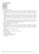
L0: Inverter module protection
Note:
1. Make sure wire connection of CN38 port of compressor inverter module board is firm. Plug or pull out the wire under live working is not allowed.
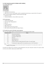
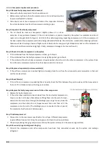
How to determine whether the compressor module is damaged?
IPM internal rectifier circuit
IPMM internal inverter circuit
Three phase rectifier measure
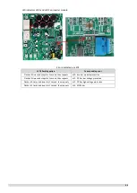
Set the multimeter to diode position. After unit power off for 10min, put the black pin on CN5(P_OUT) and put the red pin on CN6(L1)
、
CN7(L2)
、
CN11(L3)
respectively. If the voltage value is 0V, it means the three phase rectifier bridge reactor is damaged. Similarly, put the red pin on CN38 (N) and put the black pin
on CN6 (L1), CN7 (L2) and CN11 (L3) respectively. If the voltage value is 0V, it means the three phase rectifier bridge reactor is damaged.
Inverter circuit measure
Set the multimeter to diode position. After unit power off for 10min, put the black pin on CN1(P_in) and put the red pin on CN12(U)
、
CN13(V)
、
CN14(W)
respectively. If the voltage value is 0V, it means the IGBT or freewheel diode is damaged. Similarly, put the red pin on CN38 (N) and put the black pin on CN12 (U),
CN13 (V) and CN14 (W) respectively. If the voltage value is 0V, it means the IGBT or freewheel diode is damaged.
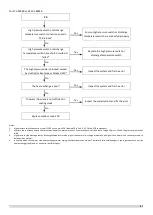
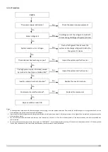
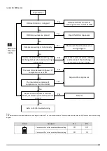
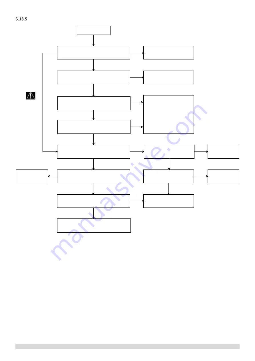
L0 protection
The DC bus wire connected incorrectly
1
Ensure the wire is
connected properly
The compressor wiring is connected
incorrectly
Reconnect the cables
based on wiring diagram
Replace the compressor
The inverter module is not well heat
dissipation
The IPM screws is loosen
Fasten IPM
screws again
The silica gel is coated not
well for heat radiation
Coat with silica
gel
The compressor has less than 12 hours
preheating before initial operating
Switch on power again to detect
whether the compressor can start
Refer to “P3 over current protection”
Replace the inverter
module
Ensure enough
preheating time
No
No
No
No
No
No
Yes
Yes
Yes
Yes
Yes
Yes
Yes
No
Yes
Yes
No
No
Disconnect
the power
supply
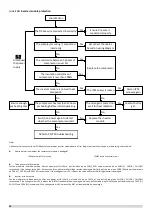
The resistance between 3 phases of
compressor is over 5Ω
The insulation resistance of
compressor is less than 100kΩ
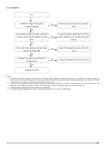
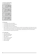
Refer to P4/P5 troubleshooting
Содержание SCV-1400EB
Страница 2: ......
Страница 4: ...2...
Страница 8: ...6...
Страница 26: ...24...
Страница 46: ...44 1 Electric Control Box Layout For SCV 750EB For SCV 1400EB...
Страница 61: ...59 3 Wiring diagram 3 1 Single unit For SCV 750EB and SCV 1400EB...
Страница 62: ...60 For SCV 900EB...
Страница 63: ...61 For SCV 1800EB...
Страница 78: ...76 5 5 E3 E4 E5 E7 Eb Ed EE EF EP EU Fb Fd Troubleshooting Digital display output...
Страница 159: ......
Страница 160: ...0 1 234 56 0 7 8 234 0 9 1 7 1 0 6 16 3 5 9 4 260 88 4 260 88 08 88 688 0 4 08 4 6 4A8 60 B...


