26
1
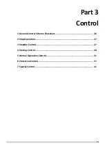
General Control Scheme Flowchart
Note:
1.
Numbers in the top right-hand corners of boxes indicate the relevant section of text on the following pages.
Easy control
Conditions met
for defrosting
On
Special control
Outdoor unit duty cycling
TEMP-SWITCH control
Defrosting operation
7
Stop operation
Abnormal shutdown
System stops
2
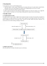
Standby control
Crankcase heater control
Water pump control
3
Startup control
Compressor startup delay control
Startup control for heating operation
Startup control for cooling operation
4
Normal operation control
Component control during normal operation
Compressor output control
Compressor step control
Water pump select control
Four-way valve control
Electronic expansion valve control
Outdoor fan control
5
Protection control
High pressure protection control
Low pressure protection control
Discharge temperature protection control
Compressor and Inverter Module Protection Control
Voltage protection control
DC fan motor protection control
Water side heat exchanger anti-freeze protection control
Air side heat exchanger high temperature protection control
Water side heat exchanger temperature difference protection control
Water side heat exchanger low temperature protection control
Water side heat exchanger low pressure protection control
6
Содержание SCV-1400EB
Страница 2: ......
Страница 4: ...2...
Страница 8: ...6...
Страница 26: ...24...
Страница 46: ...44 1 Electric Control Box Layout For SCV 750EB For SCV 1400EB...
Страница 61: ...59 3 Wiring diagram 3 1 Single unit For SCV 750EB and SCV 1400EB...
Страница 62: ...60 For SCV 900EB...
Страница 63: ...61 For SCV 1800EB...
Страница 78: ...76 5 5 E3 E4 E5 E7 Eb Ed EE EF EP EU Fb Fd Troubleshooting Digital display output...
Страница 159: ......
Страница 160: ...0 1 234 56 0 7 8 234 0 9 1 7 1 0 6 16 3 5 9 4 260 88 4 260 88 08 88 688 0 4 08 4 6 4A8 60 B...


