background image

RECOMMENDED TOOLS & TEST 
EQUIPMENT

The following list of Tools, Electrical Engineering Test Equipment and Materials are 
required to carry out the Assembly procedures contained in this document.

TOOLS

Electric Drill (preferably with Hammer Action).

a.  7.5 mm Drill Bit.
b.  Spirit Level.
c.  Pozidriv Screwdriver.

TEST EQUIPMENT

a.  Anritsu/Wiltron S331A Test Set.
b.  Earth Bonding Test Set.
c.  Dummy Load.
d.  Wattmeter (50 Ω Test Set).

CABLES

a.  USB Cable.
b.  Ethernet Switch Cable.

MATERIALS

a.  4 x M4 x 12 Screws (supplied).
b.  4 x Rawlplugs (supplied).
c.  4 x No. 12 x 1½” Woodscrews (supplied).
d.  M6 x 12 mm Pan Head Pozidriv Retaining Bolts.
e.  M6 x 16 mm Pan Head Pozidriv Retaining Bolts.
f.  M6 Nuts and Plain Washers.
g.  Plastic Cup Washers.
h.  M6 Cage Nuts.OTHER ITEMS
i.  Personal Computer (PC) with the following Software Applications 

installed:

SOFTWARE

a.  System Digital Management Terminal (SDMT).
b.  IP Configuration Tool


Doc Number:

TNM-I-E-0046 ISSUE 1.2

Page

23

Содержание SDB680

Страница 1: ...44 0 1332 375501 www simocowirelesssolutions com 1270 Ferntree Gully Road Scoresby Victoria 3179 Australia Tel 61 0 3 9730 3999 Fax 61 0 3 9730 3988 www simocowirelesssolutions com SDB680 BASE STATIO...

Страница 2: ...This page has been intentionally left blank Doc Number TNM I E 0046 ISSUE 1 2 Page 2...

Страница 3: ...otocopied reproduced translated stored or reduced to any electronic medium or machine readable form without prior written permission from Simoco COMPUTER SOFTWARE COPYRIGHTS The AMBE 2TM voice coding...

Страница 4: ...nt Simoco reserves the right to update the equipment or this document or both without prior notice ERRORS AND OMISSIONS The usefulness of this publication depends upon the accuracy and completeness of...

Страница 5: ...es 1 2 Minor Updates Mark Preston RELATED DOCUMENTS 1 TNM M E 0047 SDB680 Base Station Service Manual 2 TNM U E 0112 Simoco Digital Management Terminal User Manual 3 TNM U E 0120 Simoco IP Configurati...

Страница 6: ...REQUENCY RADIATION FCC 12 FCC PART 15 COMPLIANCE 13 EQUIPMENT SAFETY 14 INSTALLATION AND MAINTENANCE 14 CAUTIONS 14 MAINTENANCE PRECAUTIONS 14 WASTE ELECTRICAL AND ELECTRONIC EQUIPMENT WEEE NOTICE 15...

Страница 7: ...ED 39 6 1 SDB680 PREPARATION 39 6 2 SDMT INSTALLATION AND PREPARATION 40 6 3 INSTALLING THE SIMOCO IP CONFIGURATION SERVER 40 6 4 IP ADDRESS CONFIGURATION 40 6 5 CONFIGURING THE DMR BASE 41 7 CONFIGUR...

Страница 8: ...n Creation and Upload 53 8 4 5 Enable New Tier III Base 53 9 BASE CONFIGURATION TIER III TO TIER II 54 TOOLS TEST EQUIPMENT AND MATERIALS REQUIRED 54 9 1 TIER II BASE PREREQUISITES 54 9 2 IP ADDRESS C...

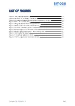
Страница 9: ...re 5 Keyhole Standoff mounting locations 36 Figure 6 Base Station secured to Wall Mount 36 Figure 7 Interface Selection screen 40 Figure 8 IP Configuration Tool main screen 41 Figure 9 Base configurat...

Страница 10: ...ctor Pin outs 30 Table 3 USB Type A Connector Pin outs 31 Table 4 USB Type B Connector Pin outs 31 Table 5 Ethernet RJ45 Connector Pin outs 31 Table 6 S2 Serial Port Connector Pin outs 32 Table 7 Faci...

Страница 11: ...t that has been switched off for maintenance Refer to the relevant Electrical Safety Regulations appropriate to the country of operation Where dangerous voltages are exposed during a task safety perso...

Страница 12: ...DANGEROUS VOLTAGES Dangerous voltages exist in this equipment for the appropriate Safety precautions refer to the relevant Electrical Safety Regulations appropriate to the country of operation WARNING...

Страница 13: ...T 15 COMPLIANCE THIS DEVICE COMPLIES WITH PART 15 OF THE FCC RULES OPERATION IS SUBJECT TO THE FOLLOWING TWO CONDITIONS 1 THIS DEVICE MAY NOT CAUSE HARMFUL INTERFERENCE AND 2 THIS DEVICE MUST ACCEPT A...

Страница 14: ...O NOT use the front panel attachment points to support the full weight of the equipment or damage to the equipment may result Suitable shelves or supports MUST be provided to support the body of the b...

Страница 15: ...art of the legislation electrical and electronic equipment will feature the crossed out wheeled bin symbol see image at left on the product or in the documentation to show that these products must be...

Страница 16: ...vices Email inquiry aus simocowirelesssolutions com Telephone Numbers Australia 1300 363 607 International 61 3 9730 3999 US Customer Services Email customer service simocowirelesssolutions com Techni...

Страница 17: ...via the Technical Support Helpline numbers below Technical Support Email Addresses Simoco EMEA technical support simocowirelesssolutions com Simoco Aus tralasia inquiry aus simocowirelesssolutions co...

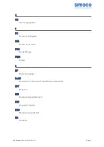
Страница 18: ...achine B BER Bit Error Rate C CLI Command Line Interface CRC Cyclic Redundancy Check CTS Clear To Send D dBc decibel relative to the carrier dBi decibel relative to the isotropic dBm decibel relative...

Страница 19: ...al Equipment E EMC Electro Magnetic Compatibility F FCC Federal Communications Commission FEC Forward Error Correction FEP Front End Processor G GPL General Public License H HTTPS Hypertext Transfer P...

Страница 20: ...Access Control MDIX Medium Dependant Interface Crossover MIB Management Information Base MRU Maximum Recption Unit MTU Maximum Transmission Unit N NC Normally Closed NMS Network Management System NO N...

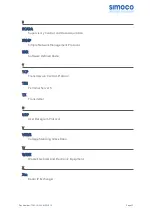
Страница 21: ...Error Rate POS Point Of Sale PWR Power R RF Radio Frequency RoHS Restriction of the use of Hazardeous Substances RPT Repeater RSS Received Signal Strength RTS Request To Send RTU REmote Terminal Unit...

Страница 22: ...ocol SNR Software Defined Radio T TCP Transmission Control Protocol TS5 Terminal Server 5 TX Transmitter U UDP User Datagram Protocol V VSWR Voltage Standing Wave Ratio W WEEE Waste Electrical and Ele...

Страница 23: ...ding Test Set c Dummy Load d Wattmeter 50 Test Set CABLES a USB Cable b Ethernet Switch Cable MATERIALS a 4 x M4 x 12 Screws supplied b 4 x Rawlplugs supplied c 4 x No 12 x 1 Woodscrews supplied d M6...

Страница 24: ...ng airflow is critical to the performance of the base station Whether wall mounted or rack mounted always ensure that there is adequate ventilation around the base station The ambient temperature must...

Страница 25: ...closely you comply with the airflow requirements described above In a wall mount installation it is recommended that at least 20 cm of clear space is allowed above and below the equipment for ventilat...

Страница 26: ...Doc Number TNM I E 0046 ISSUE 1 2 Page 26...

Страница 27: ...ccupy a total of either 3U or 4U of rack space The tray is supplied complete with a universal power supply which can accept an IEC input of 100 V to 240 V AC Voltage Alternating Current at 50 60 Hz su...

Страница 28: ...80 Base Station is supplied with a 2 pin IP67 DC Connector that should be used to connect the DC power to the base station When considering the cable to use with this connector users should Doc Number...

Страница 29: ...damage from vermin or adverse environments Multi strand wires must be used wherever the wire will be flexed by accessing the equipment 3 2 REAR PANEL CONNECTORS The rear panel of the SDM680 DMR base...

Страница 30: ...and gold centre pin to minimise passive intermodulation A minimum of 85 dB transmit receive isolation should be provided by the antenna system and associated filters It is recommended that a good qua...

Страница 31: ...able 3 USB Type A Connector Pin outs 3 2 5 P4 USB B The Universal Serial Bus USB Type B connector is used as the peripheral connection The connector pin outs are detailed below in Table 3 Pin Function...

Страница 32: ...Connector are shown below in Table 7 Function Pin Tier II Tier III 1 Digital Input External Alarm Input 2 Digital Input External Alarm Input 3 Digital Input External Alarm Input 4 Digital Input Extern...

Страница 33: ...ing fuse The Digital Outputs are open collector and able to sink 300 mA each the total for all outputs must not exceed 600 mA Digital inputs are active low Digital high voltages should not exceed 20 V...

Страница 34: ...ment and retain the packaging 2 Establish the mounting position of the base station CAUTION Before drilling any walls first check for any buried cables or pipes 3 Ensure that there are no buried pipes...

Страница 35: ...ition and cannot be trapped offer the base station up to the wall mount unit and fit the four keyhole standoffs on the base station two per side into the mounting grooves on the wall mount case see Fi...

Страница 36: ...or better at the relevant Tx and Rx Frequencies 3 On the SDB680 Base Station rear panel carry out the following a Connect the Tx and Rx antenna cables to their respective connectors b Ensuring that t...

Страница 37: ...te Rack runner fittings differ between the various rack manufacturers If the procedure described below does not apply to the type of rack being used the procedure should be modified to suit 1 Ensure t...

Страница 38: ...the base station onto the support brackets and slide the base station into the rack checking that it does not catch on anything 4 Secure the base station into the rack using the four M6 x 12 mm pozid...

Страница 39: ...sword will be required ii To request access to the partner portal please contact your local business development manager or alternatively contact the relevant Simoco Customer Services see Support Page...

Страница 40: ...nd install the Simoco IP Configuration Server software in accordance with Todo Section 1 3 Software Installation 2 After installing the Simoco IP Configuration Tool software ensure that the PC on whic...

Страница 41: ...DMR Tier II tab 3 On the Site View tab of the Navigation Pane from the navigation tree click on the System branch to expand it Click on the Site 1 node displayed 4 On the Ribbon bar select the Add Dig...

Страница 42: ...ee Figure 10 and any open base configuration pages will be closed 10 On the Write Base s page carry out the following a Select the new DMR Base that is included in the working configuration b Select t...

Страница 43: ...access the Partner Portal a Username and Password will be required ii To request access to the partner portal please contact your local business development manager or alternatively contact the releva...

Страница 44: ...following 2 Install the SDMT software in accordance with Todo Section 1 2 Software Installation 3 Prepare the SDMT software for use in accordance with Todo Section 2 2 SDMT Preparation 4 Create or es...

Страница 45: ...ress listed in the data grid of the main screen in accordance with Todo Section 2 2 Configuring an IP Address 7 6 CONFIGURING THE DMR BASE 7 6 1 Platform and Application Software Update 1 On the PC op...

Страница 46: ...en in accordance with Todo Section 2 2 Configuring an IP Address above and Todo Para 2 3 of Section 2 2 Configuring an IP Address in the Simoco IP Configuration Tool User Manual for clarification 6 On...

Страница 47: ...area after a short delay confirm that a Completed Update Software message is displayed 7 6 3 Configuration Creation and Upload 1 Refer to Part 3 of the SDMT User Manual and create a working configurat...

Страница 48: ...tes enable warning message will be displayed b To enable an individual base carry out the following i Right click on the Base that you wish to enable Menu options will be displayed ii From the menu op...

Страница 49: ...o Customer Services see Support Page for details 8 1 TIER III BASE PREREQUISITES Before commencing this procedure to configure a Tier II Base Station into a Tier III Base Station it is assumed that th...

Страница 50: ...ss the Simoco webpage 2 On the Simoco webpage select Partner Login and login to the Partner Portal area https www simocogroup com portal partner login 3 When logged in to the Partner Portal navigate t...

Страница 51: ...will be displayed 8 On the Open file window navigate to and select the latest version of the DMR Tier III Application Software downloaded at Para 10 Select the Open button to load the file into the S...

Страница 52: ...stem I O page select the Browse button for the Licence file An Open file dialogue window will be displayed 2 On the Open file window navigate to and select the relevant software licence file Select th...

Страница 53: ...Subscribers or both Select the Write to System button ii In the Comms History area confirm that a Starting Write All Config message is displayed iii The progress of the write operation will be display...

Страница 54: ...ant Simoco Customer Services see Support Page for details 9 1 TIER II BASE PREREQUISITES Before commencing this procedure to configure a Tier III Base Station into a Tier II Base Station it is assumed...

Страница 55: ...If necessary download the latest software to the PC Note The versions of DMR Base software listed and available on the Partner Portal contain two software files These are the Cerebral Platform softwar...

Страница 56: ...t the following i Select the base you wish to upload the software to ii Select the Upload button to programme the base with the Application Software and the Cerebral Platform b On the DMR Tier II ribb...

Страница 57: ...To complete the software configuration update procedure for the selected DMR Base the base must be re booted Doc Number TNM I E 0046 ISSUE 1 2 Page 57...

Страница 58: ...This page has been intentionally left blank...

Страница 59: ...Simoco Wireless Solutions Field House Uttoxeter Old Road Derby DE1 1NH Tel 44 0 1332 375500 Fax 44 0 1332 375501 www simocowirelesssolutions com...

Отзывы: