The installation must be understood as fixed,
and must be carried out by a qualified spe-
cialist company, and in compliance with all
the instructions and provisions given in this
manual.
Installation must also conform with the pre-
scriptions of UNI-CIG, CEI Standards, and
with those laid down by the public health
authorities.
2.1
FIXING THE BOILER
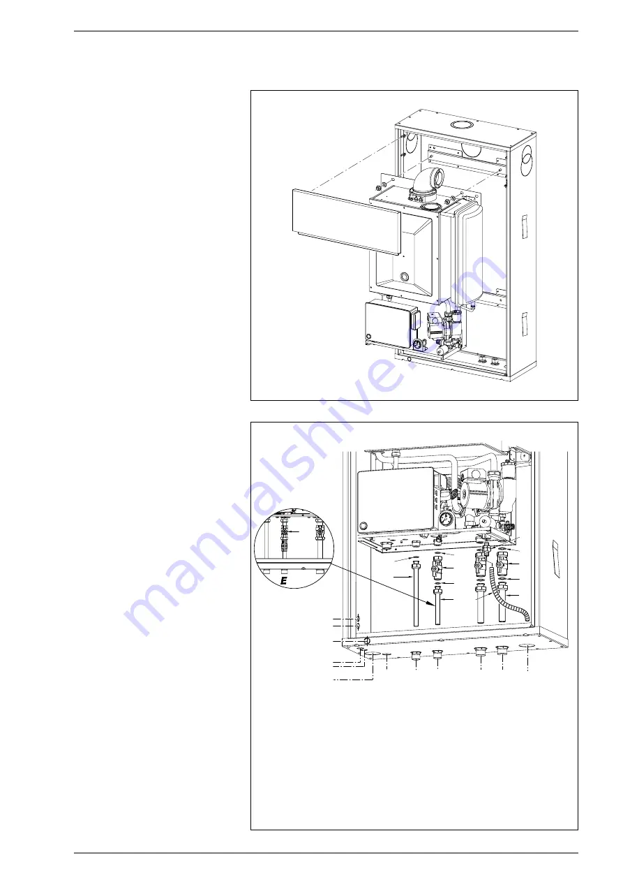
Assembly of the boiler inside the frame for
in-built installation is facilitated by the large
opening. The boiler must be inserted onto
the special pins on the bottom of the frame
and locked in place with the nuts and
washers provided (fig. 4).
2.1.1
Plant connections kit
To fit the components of the kit supplied
with the boiler, follow the instructions in fig.
5.
2.2
PLANT CONNECTION
To protect the burner system from dama-
ging corrosion, encrustations or deposits, it
is extremely important, before installing the
appliance, to wash the plant pursuant to
Standard UNI-CTI 8065, using suitable pro-
ducts such as, for example, Sentinel X300
or X400.
Full instructions are given with the pro-
ducts, but for further information, you can
contact the producer GE Betz srl directly.
After washing the plant, the use of Sentinel
X100 type inhibitors is recommended to
protect it against corrosion and deposits.
It is important to check the concentration
of the inhibitor after every modification to
the plant and af ter every maintenance
check, pursuant to the manufacturer’s pre-
scriptions (special test kits are available-
from dealers).
The discharge of the safety valve must be
connected to a collection funnel which
channels off any discharge in the case of
intervention.
IMPORTANT:
- In the case of failure to wash the plant
and to apply a suitable inhibitor, the
appliance guarantee shall be null and
void.
- Since the boiler is installed out of
doors, a good antifreeze liquid, of a
recognised brand, should be introduced
into the boiler, following the manufactu-
rers instructions on the percentages to
be used.
The gas supply must be connected in com-
pliance with Standards UNI 7129/92 and
UNI 7131/99.
56
1
2
3
1
1
4
6
5
5
7
Scarico condensa
Attacco gas
in alternativa
Collegamenti
elettrici
8
9
Collegamenti
elettrici
G
U
E
M
R
S
3
KEY
1
Washer ø 18,5
2
Small pipe length 1/2” x 14 L. 200
3
Sanitary water input tap 1/2” MF
4
Small pipe length 1/2” x 14 L. 120
5
Washer ø 24
6
Plant input/return tap 3/4” MF
7
Small pipe length 3/4” x 18 L. 120
8
Connection
9
Discharge pipe safety valve
Fig. 5
2
INSTALLATION
Fig. 4
Electrical
connections
Alternative gas
connection
Electrical
connections
Condensation outlet
Содержание Open.zip 25 BF TS
Страница 1: ...GB Open zip 25 30 BF TS IT ES CERTIFICAZIONE DEL SISTEMA DI QUALITA AZIENDALE...
Страница 28: ...26...
Страница 52: ...50...
Страница 54: ...52...
Страница 79: ......


