background image

82

4.4

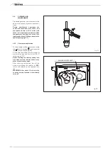
CLEANING AND 
MAINTENANCE

Scheduled generator maintenance must be
performed annually by authorised techni-
cians.

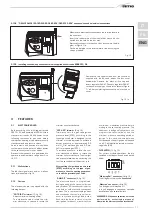
During maintenance operations the
authorised technician must check that
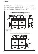
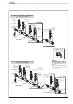
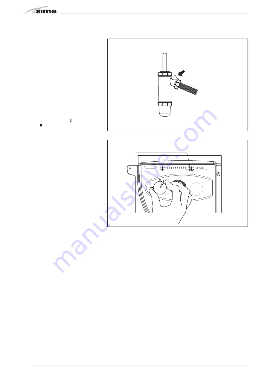
the syphened drip is full of water (this
check is of importance particularly when
the generator has been out of use for a
long period of time). Filling is done via the
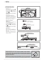
special opening (fig. 21).

4.4.1

Chimney sweep function

To check single module combustion, rotate
the selector to position ( ) until the yellow
led (

) starts to blink (fig. 22). 

At this time the module will start to heat at
maximum power and turn of f at 80°C,
restarting at 70°C.

Before starting the chimney sweep func-
tion, make sure the radiator valves or any
other area valves are open. 

After checking combustion, turn off the
module by rotating the selector to (

OFF

);

return the selector to the required func-
tion.

WARNING: After about 15 minutes the
chimney sweep function automatically
turns off.  

SPIA GIALLA INTERMITTENTE

Fig. 22

BLINKING YELLOW LIGHT

Fig. 21

Содержание DEWY EQUIPE 120 BOX

Страница 1: ...ISO 9001 2000 CERTIFIED COMPANY DEWY EQUIPE 60 360 BOX P60 P120 BOX Fonderie SIME S p A Cod 6295220A 01 11 IT ES ENG ...

Страница 2: ......

Страница 3: ...preso quello del bruciatore Accertarsi che la caldaia sia predisposta al funzionamento per il tipo di gas erogato Verificare che il condotto di evacuazione dei prodotti della combustione sia libero e o sia stato montato cor rettamente Accertarsi che le eventuali saracinesche siano aperte Assicurarsi che l impianto sia stato caricato d acqua e risulti ben sfiatato Verificare che il circolatore non ...

Страница 4: ...945 180 90 155 403 640 637 342 440 810 G S3 M R DEWY EQUIPE 60 BOX P60 BOX 180 90 155 403 640 637 342 440 810 G S3 M R 355 695 1600 1945 415 260 675 1100 1775 470 390 DEWY EQUIPE 120 BOX P120 BOX Fig 1 ATTACCHI M Mandata impianto G 2 UNI ISO 7 1 R Ritorno impianto G 2 UNI ISO 7 1 G Gas Flangia PN6 DN50 S3 Scarico condensa ø 40 NOTA Possibilità di attacco sul lato dx spostando le flange cieche dei ...

Страница 5: ...O 7 1 R Ritorno impianto G 2 UNI ISO 7 1 G Gas Flangia PN6 DN50 S3 Scarico condensa ø 40 NOTA Possibilità di attacco sul lato dx spostando le flange cieche dei collettori mandata ritorno impianto e richiedendo a parte il kit sicurezze ISPESL cod 8101511 Il montaggio del kit sicurezze ISPESL è obbligatorio e nelle installazioni esterne deve obbligatoriamente essere inserito nell apposito box cod 81...

Страница 6: ...N80 R Ritorno impianto Flangia PN6 DN80 G Gas Flangia PN6 DN50 S3 Scarico condensa ø 40 NOTA Possibilità di attacco sul lato dx spostando le flange cieche dei collettori mandata ritorno impianto e richiedendo a parte il kit sicurezze ISPESL cod 8101511 Il montaggio del kit sicurezze ISPESL è obbligatorio e nelle installazioni ester ne deve obbligatoriamente essere inserito nell apposito box cod 81...

Страница 7: ...Q Nominale 80 60 C C 68 68 68 68 68 68 Temperatura fumi a Q Minima 80 60 C C 58 58 58 58 58 58 Temperatura fumi a Q Nominale 50 30 C C 49 49 49 49 49 49 Temperatura fumi a Q Minima 50 30 C C 42 42 42 42 42 42 Portata massima fumi kg h 95 2 190 5 285 7 380 9 476 2 571 4 CO2 a Q Nominale Minima G20 9 0 9 0 9 0 9 0 9 0 9 0 9 0 9 0 9 0 9 0 9 0 9 0 CO2 a Q Nominale Minima G31 10 0 10 0 10 0 10 0 10 0 1...

Страница 8: ...11 Termostato fumi 12 Scambiatore primario 13 Diaframma 14 Pressostato differenziale 15 Trasduttore pressione acqua 16 Valvola sfogo aria 17 Valvola di ritegno 18 Circolatore 19 Manometro 0 6 BAR con rubinetto 20 Pressostato acqua di minima 21 Termostato sicurezza 100 C 22 Rubinetto di scarico a tre vie 23 Rubinetto mandata impianto 24 Scarico singolo modulo 25 Rubinetto gas 26 Vaso espansione lit...

Страница 9: ...lettrodo rivelazione 9 Trasformatore d accensione 10 Termostato fumi 11 Pannello comandi 12 Presa analisi fumi 13 Pressostato aria 14 Sonda riscaldamento SM 15 Termostato sicurezza 95 C 16 Pressostato differenziale 17 Sfiato automatico 18 Valvola di ritegno 19 Circolatore 20 Valvola sicurezza 4 BAR 21 Scarico modulo 22 Rubinetto mandata impianto 23 Rubinetto di scarico a tre vie 24 Scatola di deri...

Страница 10: ...01551 per i moduli 300 360 BOX Kit collettore fumi in polipropilene per installazioni interne appositamente trat tati per resistere agli agenti atmosferici nel caso di installazioni esterne cod 8102510 per il modulo 60 P60 BOX cod 8102511 per il modulo 120 P120 BOX cod 8102512 per il modulo 180 BOX cod 8102513 per il modulo 240 BOX cod 8102514 per il modulo 300 BOX cod 8102515 per il modulo 360 BO...

Страница 11: ...da contatore a modulo si dovrà tene re conto sia delle portate in volumi consu mi in m3 h che della densità del gas preso in esame Le sezioni delle tubazioni costi tuenti l impianto devono essere tali da garantire una fornitura di gas sufficiente a coprire la massima richiesta limitando la perdita di pressione tra contatore e qual siasi apparecchio di utilizzazione non mag giore di 1 0 mbar per i ...

Страница 12: ...draulico kit sicurezze ISPSEL cod 8101517 Nelle figure 6 c e 6 d sono indicati invece gli elementi inclusi nel kit collettore fumi in polipropilene necessari all installazione sin gola che ai vari abbinamenti dei moduli e gli accessori disponibili a richiesta da utilizzare a seconda della tipologia di installazione NOTA I kit sono appositamente trattati anche per resistere agli agenti atmosferi ci...

Страница 13: ...raulico kit sicurezze ISPESL DEWY EQUIPE 240 BOX Kit collettore fumi uscita lato dx e box contenitore separatore idraulico kit sicurezze ISPESL Ø 160 H Prolunga L 500 da richiedere a parte cod 8102522 Prolunga L 1000 da richiedere a parte cod 8102523 Fig 6 a H 120 P120 BOX 470 180 BOX 525 240 BOX 525 ...

Страница 14: ... 300 BOX Kit collettore fumi uscita lato dx e box contenitore separatore idraulico kit sicurezze ISPESL ø 160 ø 200 420 560 Prolunga L 500 da richiedere a parte cod 8102522 DEWY EQUIPE 360 BOX Kit collettore fumi uscita lato sx e box contenitore separatore idraulico kit sicurezze ISPESL 585 ø 160 ø 200 Prolunga L 1000 da richiedere a parte cod 8102523 Fig 6 b ...

Страница 15: ...96514 L 630 cod 6296516 cod 6296500 Curva n 3 cod 6296507 A 133 mm cod 6296513 x 3 Curva n 2 cod 6296506 A 104 mm cod 6296515 L 470 cod 6296514 L 630 Curva n 4 cod 6296508 A 158 mm cod 6296518 cod 6296510 ø 125 L 1000 Curva a 90 ø 125 cod 6296519 cod 6296513 Cod 5192906 Cod 5192905 Cod 5192905 Cod 8102511 Fig 6 c ATTENZIONE Per facilitare l accoppiamento degli elementi che compongono il collet tor...

Страница 16: ...13 x 5 Curva n 1 cod 6296505 A 78 mm cod 6296515 L 470 cod 6296514 L 630 Curva n 4 cod 6296508 A 158 mm Curva n 3 cod 6296507 A 133 mm cod 6296515 L 470 Cod 5192905 Curva n 5 cod 6296523 A 213 mm cod 6296525 Ø 200 Cod 5192907 Cod 8102511 cod 6296526 Ø 160 200 Curva n 6 cod 6296524 A 238 mm cod 6296525 Ø 200 Cod 5192908 A KIT COLLETTORE FUMI cod 8102515 DEWY EQUIPE 360 BOX KIT COLLETTORE FUMI cod 8...

Страница 17: ...20 C 1 2 cod 6146004 Valvola di sicurezza 3 5 BAR cod 6042203 e imbuto di scarico cod 6269402 Termostato sicurezza 100 C riarmo manuale cod 6001409 Pressostato acqua di massima 4 BAR 1 4 cod 6037550 Pressostato acqua di minima 0 9 BAR 1 4 cod 6337551 Blocchetto di collegamento pressostati cod 6291981 e curvette cod 6291982 Manometro 0 6 BAR 1 4 cod 6217050 rubinetto cod 6216606 e ric cio cod 62166...

Страница 18: ...egolatore RVA 47 R1 Resistenza 536 Ohm 1 R2 Resistenza 562 Ohm 1 R3 Resistenza 604 Ohm 1 R4 Resistenza 649 Ohm 1 1 Le resistenze sono fornite nel kit di sequenza cascata RVA 47 cod 8096301 08 NOTA Per il collegamento di altri accessori al regolatore RVA 47 pompa impianto sonda temperatura esterna sonda mandata cascata ecc vedere il manuale istruzioni fornito nell apposito kit cod 8096301 08 Fig 7 ...

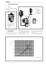
Страница 19: ...mpleto di guarnizioni dadi e viti di fissaggio fig 8 a ATTENZIONE E possibile inserire il com pensatore idraulico in un apposito box di protezione cod 8101517 da richiedere a parte 2 9 3 Perdite di carico del compensatore idraulico fig 9 Le perdite di carico del separatore idrauli co sono indicate nei diagrammi di fig 9 19 IT ES ENG Fig 8 80 100 120 140 2 PORTATA m3 h 4 6 8 10 12 0 20 40 60 p mbar...

Страница 20: ...modulo Caldaia 1 2 3 o 4 NOTA I trimmer MAX e MIN della scheda controllo ventilatore SV sono sigillati e per nessuna ragione devono essere manomessi CODICI RICAMBI CONNETTORI J2 cod 6278613 J3 cod 6299971 J4 cod 6293595 J5 cod 6293594 J7 cod 6293593 Fig 11 2 10 ALLACCIAMENTO ELETTRICO Ogni modulo è fornito con cavo elettrico di alimentazione che in caso di sostituzione dovrà essere richiesto alla ...

Страница 21: ...il box ed inclinare verso il basso la copertura della scatola Togliere il copriforo nero ed inserire il regolatore RVA 47 Collegare elettricamente il regolatore RVA 47 come indicato dallo schema riportato in fig 7 a Completato il collegamento richiudere la copertura della scatola 2 10 2 Collegamento elettrico dei moduli DEWY EQUIPE 120 180 240 300 360 BOX P120 BOX fig 12 Fig 12 Fig 12 a 2 10 3 Mon...

Страница 22: ... e spegni menti con intervalli molto ristretti che in particolare si potrebbero verificare in impianti ad elevate perdite di carico Ad ogni ripartenza dopo il periodo di lenta accensione la caldaia si posizio nerà per circa 1 minuto alla pressione minima di modulazione per poi riportarsi al valore di pressione riscaldamento impostato Con l inserimento del ponte si annulleranno sia la sosta tecnica...

Страница 23: ...cchiatura che possia mo così riassumere L elettrodo di accensione non emette la scarica Nella caldaia si nota solamente l apertura del gas al bruciatore trascorsi 10 sec si accende la spia di blocco Può essere causato dal fatto che il cavo dell elettrodo risulta interrotto o non è ben fissato al morsetto del trasformato re d accensione Non c è rilevazione di fiamma Dal momento dell accensione si n...

Страница 24: ...quale si dovranno allaccia re i termostati ambiente con relative valvo le o pompe di zona Il collegamento dei micro o dei contatti relè va effettuato sul connettore della scheda elettronica J2 dopo aver tolto il ponte esi stente fig 17 CR1 CR TA 5 SONDA SANITARIO CONNETTORE J2 COPERTURA TA 6 SB 11 SB 12 CIRCUITO CON VALVOLE DI ZONA NOTA I relé vengono impiegati solo nel caso le valvole di zona sia...

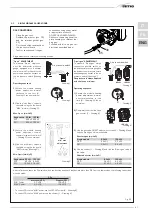
Страница 25: ...rio La potenzialità a cui è tarato il singolo modulo può essere verificata misurando il p aria con un manometro digitale collegato come indicato in fig 19 I valori ottenuti dovranno corrispondere a quelli riportati nel diagram ma di fig 19 a 4 USO E MANUTENZIONE 1 2 3 4 5 6 Fig 18 LEGENDA 1 Presa pressione a monte 2 Presa pressione intermedia 3 Ingresso segnale aria 4 Presa pressione a valle 5 Par...

Страница 26: ... 100 kW 1 2 60 kW 100 kW 2 1 Terminate le operazioni di taratura verificare i valori di CO2 con un analizzatore di combustione Qualora si riscontrino discordanze superiori o inferiori allo 0 2 rispetto ai valori indicati in tabella è necessario effettuare le oppurtune correzioni Per correggere la CO2 alla potenza MIN agire sulla vite OFF SET 2 Disegno 6 Per correggere la CO2 alla potenza MAX agire...

Страница 27: ... 22 Per effettuare la verifica di combustione del singolo modulo ruotare il selettore e sostare su posizione fino a quando il led giallo non inizia a lampeggiare fig 22 Da quel momento il modulo inizierà a funzionare in riscaldamento alla massima potenza con spegnimento a 80 C e riac censione a 70 C Prima di attivare la funzione spazzacami no accertarsi che le valvole radiatore o eventuali valvole...

Страница 28: ...ell acqua è inferiore a circa 55 C si ottie ne la condensazione dei prodotti della com bustione che incrementa ulteriormente l efficienza dello scambio termico TRASFORMAZIONE GAS Nel caso si renda necessaria la trasforma zione ad altro gas rivolgersi esclusivamente al personale tecnico autorizzato SIME PULIZIA E MANUTENZIONE La manutenzione programmata del gene ratore va effettuata annualmente com...

Страница 29: ... rosso intermittente 35 C Per ritentare l accensione si dovrà ruo tare la manopola del selettore in posizio ne e rilasciarla subito dopo riponen dola in inverno Se si dovesse verificare nuovamente il blocco richiedere l intervento del Servi zio Tecnico Autorizzato per un controllo Altre anomalie fig 6 Quando lampeggia uno dei led rossi da 40 80 C disattivare il generatore e ritentare l accensione ...

Страница 30: ... la propria firma per accettazione L Utente dovrà conservare la propria copia da esibire al Centro Assistenza Autorizzato in caso di necessità oppure nel caso non sia stata effettuata la verifica iniziale dovrà esibi re la documentazione fiscale rilasciata all acquisto dell appa recchio Per le caldaie a gasolio esclusi i gruppi termici le caldaie a legna carbone escluse le caldaie a pellet e gli s...

Страница 31: ...a 0386 916055 Gazoldo degli Ippoliti Franzoni Bruno 0376 657727 Guidizzolo Gottardi Marco 0376 819268 Marmirolo Clima World 045 7950614 Poggio Rusco Zapparoli William 0386 51457 Porto Mantovano Clima Service 0376 390109 Roncoferraro Mister Clima 0376 663422 Roverbella Calor Clima 0376 691123 S Giorgio Rigon Luca 0376 372013 Cortatone Rodolfi Mirko 0376 49522 PAVIA Pavia Ferrari s r l 0382 423306 G...

Страница 32: ...esaproba Cordeschi Berardino 0862 908182 Cese di Preturo Maurizi Alessio 0862 461866 Pratola Peligna Giovannucci Marcello 0864 272449 CAMPOBASSO Termoli G S SERVICE 0875 702244 Campobasso Catelli Pasqualino 0874 64468 CHIETI Chieti Almagas 085 810938 Fara S Martino Valente Domenico 0872 984107 Francavilla al Mare Disalgas 085 4910409 Francavilla al Mare Effedi Impianti 085 7931313 Lanciano Frances...

Страница 33: ...ble Comprobar que el conducto de evacuación de los productos de la combustión esté libre y o esté monta do correctamente Comprobar que las eventuales válvulas de compuerta estén abiertas Comprobar que la instalación esté llena de agua y que esté bien purgada Comprobar que el circulador no esté bloqueado Purgar el aire presente en la tubería del gas actuando sobre el purgador de toma de presión sit...

Страница 34: ... 1945 180 90 155 403 640 637 342 440 810 G S3 M R DEWY EQUIPE 60 BOX P60 BOX 180 90 155 403 640 637 342 440 810 G S3 M R 355 695 1600 1945 415 260 675 1100 1775 470 390 DEWY EQUIPE 120 BOX P120 BOX Fig 1 CONEXIONES M Ida instalación G 2 UNI ISO 7 1 R Retorno instalación G 2 UNI ISO 7 1 G Gas Brida PN6 DN50 S3 Descarga agua de condensación ø 40 NOTA Posibilidad de conexión en el lado derecho despla...

Страница 35: ...Retorno instalación G 2 UNI ISO 7 1 G Gas Brida PN6 DN50 S3 Descarga agua de condensación ø 40 NOTA Posibilidad de conexión en el lado derecho desplazando las bridas ciegos de los colectores impulsión retorno de la instalación y solicitando aparte el kit de seguridades cód 8101511 El montaje del kit seguridades es obligatorio y las insta laciones al aire libre debe ser necesariamente incluidos en ...

Страница 36: ...Retorno instalación Brida PN6 DN80 G Gas Brida PN6 DN50 S3 Descarga agua de condensación ø 40 NOTA Posibilidad de conexión en el lado derecho desplazando las bridas ciegos de los colectores impulsión retorno de la instalación y solicitando aparte el kit de seguridades cód 8101511 El montaje del kit seguridades es obligatorio y las instalaciones al aire libre debe ser necesariamente incluidos en el...

Страница 37: ...minal 80 60 C C 68 68 68 68 68 68 Temperatura humos a C Mínima 80 60 C C 58 58 58 58 58 58 Temperatura humos a C Nominal 50 30 C C 49 49 49 49 49 49 Temperatura humos a C Mínima 50 30 C C 42 42 42 42 42 42 Caudal máximo humos kg h 95 2 190 5 285 7 380 9 476 2 571 4 CO2 a C Nominal Mínima G20 9 0 9 0 9 0 9 0 9 0 9 0 9 0 9 0 9 0 9 0 9 0 9 0 CO2 a C Nominal Mínima G31 10 0 10 0 10 0 10 0 10 0 10 0 10...

Страница 38: ...C 11 Termostato humos 12 Intercambiador primario 13 Diafragma 14 Presostato diferencial 15 Transductor presión agua 16 Válvula purga aire 17 Válvula de retención 18 Circulador 19 Manómetro 0 6 BAR con grifo 20 Presostato agua de max 21 Termostato seguridad 100 C 22 Grifo de descarga de tres vías 23 Grifo ida instalación 24 Descarga módulo individual 25 Grifo gas 26 Vaso expansión 8 litros 27 Válvu...

Страница 39: ...Electrodo detección 9 Transformador de encendido 10 Termostato humos 11 Panel mandos 12 Toma análisis humos 13 Presostato aire 14 Sonda calefacción SM 15 Termostato seguridad 95 C 16 Presostato diferencial 17 Purgador automático 18 Válvula de retención 19 Circulador 20 Válvula seguridad 4 BAR 21 Descarga módulo 22 Grifo ida instalación 23 Grifo de descarga de tres vías 24 Caja de derivación ...

Страница 40: ...00 x 640 x 1600 para separador hidráulico kit de seguridad y circuladores cód 8101518 Kit colector humos en polipropileno para instalaciones internas tratados expresa mente para resistir a los agentes atmo sféricos en caso de instalación exterior cód 8102510 para el módulo 60 P60 BOX cód 8102511 para el módulo 120 P120 BOX cód 8102512 para el módulo 180 BOX cód 8102513 para el módulo 240 BOX cód 8...

Страница 41: ...o los caudales en volúmenes consumos en m3 h que de la densidad del gas utilizado Las secciones de las tuberías que componen la instala ción deben ser tales que se garantice un suministro de gas suficiente para atender la máxima demanda limitando la pérdida de presión entre contador y cualquier apa rato utilizador no mayor que 1 0 mbar para los gases de la segunda familia gas natu ral Dentro del m...

Страница 42: ...ican al contra rio los elementos incluidos en el kit colector humos en polipropileno necesarios sea para la instalación individual que para las varias combinaciones de los módulos y los acceso rios disponibles a petición a utilizar según el tipo de instalación NOTA Los kits son tratados expresamen te para resistir a los agentes atmosféri cos en caso de instalación exterior DEWY EQUIPE 240 BOX Kit ...

Страница 43: ...00 da richiedere a parte cod 8102522 Prolunga L 1000 da richiedere a parte cod 8102523 Fig 6 a H 120 P120 BOX 470 180 BOX 525 240 BOX 525 DEWY EQUIPE 240 BOX Kit colector humos salida lado derecho y box contenedor separador hidráulico kit seguridades DEWY EQUIPE 240 BOX Kit colector humos salida lado izquierdo y box contenedor separador hidráulico kit seguridades Alargador L 500 suministrada a par...

Страница 44: ...d 8102522 DEWY EQUIPE 360 BOX Kit collettore fumi uscita lato sx e box contenitore separatore idraulico kit sicurezze ISPESL 585 ø 160 ø 200 Prolunga L 1000 da richiedere a parte cod 8102523 Fig 6 b DEWY EQUIPE 300 BOX Kit colector humos salida lado derecho DEWY EQUIPE 300 BOX Kit colector humos salida lado derecho y box contenedor separador hidráulico kit seguridades DEWY EQUIPE 360 BOX Kit colec...

Страница 45: ...296515 L 470 cod 6296514 L 630 Curva n 4 cod 6296508 A 158 mm cod 6296518 cod 6296510 ø 125 L 1000 Curva a 90 ø 125 cod 6296519 cod 6296513 Cod 5192906 Cod 5192905 Cod 5192905 Cod 8102511 Fig 6 c ATENCIÓN Para facilitar el acoplamiento de los elementos que componen el colec tor humos untar en las juntas de estanqueidad el contenido del tubi to incluido en el suministro Prestar atención en la secue...

Страница 46: ...30 Curva n 4 cod 6296508 A 158 mm Curva n 3 cod 6296507 A 133 mm cod 6296515 L 470 Cod 5192905 Curva n 5 cod 6296523 A 213 mm cod 6296525 Ø 200 Cod 5192907 Cod 8102511 cod 6296526 Ø 160 200 Curva n 6 cod 6296524 A 238 mm cod 6296525 Ø 200 Cod 5192908 A KIT COLLETTORE FUMI cod 8102515 DEWY EQUIPE 360 BOX KIT COLLETTORE FUMI cod 8102514 DEWY EQUIPE 300 BOX Fig 6 d ATENCIÓN Para facilitar el acoplami...

Страница 47: ...s tuercas y tornillos de fijación M16 Termómetro 0 120 C 1 2 cód 6146004 Válvula de seguridad 3 5 BAR cód 6042203 y embudo de descarga cód 6269402 Termostato seguridad 100 C rearme manual cód 6001409 Presostato agua de max 4 BAR 1 4 cód 6037550 Presostato agua de min 0 9 BAR 1 4 cód 6337551 Bloque de conexión presóstatos cód 69291981 y curvas cód 6291982 Manómetro 0 6 BAR 1 4 cód 6217050 grifo cód...

Страница 48: ...ión sonda temperatu ra externa sonda impulsión cascada etc ver el manual de instrucciones que acompaña el kit cód 8096301 08 2 8 1 Conexionado eléctrico en secuencia cascada y kit seguridades fig 7 a Pmin R4 R3 R2 R4 R3 R2 DEWY EQUIPE 300 P500 P460 DEWY EQUIPE 360 P600 P560 Pmax TS CALDAIA 1 CALDAIA 2 CALDAIA 3 CALDAIA 4 DEWY EQUIPE 120 P120 P200 P160 DEWY EQUIPE 180 P300 P260 DEWY EQUIPE 240 P240...

Страница 49: ...to de juntas tuercas y tornillos de fijación fig 8 a ATENCIÓN Es posible introducir el separa dor hidráulico en un contenedor de protec ción cód 8101517 a solicitar a parte 2 9 3 Pérdidas de carga Las pérdidas de carga del separador hidráu lico se indican en el diagrama de la fig 9 49 IT ES ENG Fig 8 80 100 120 140 2 PORTATA m3 h 4 6 8 10 12 0 20 40 60 p mbar 14 16 18 160 180 200 220 240 260 Fig 9...

Страница 50: ...V2 Bobina válvula gas EA Electrodo encendido ER Electrodo detección TS Termostato seguridad 100 C V Ventilador TPA Transductor presión agua PI Bomba instalación SA Sonda anti gelo sifao SM Sonda calefacción TR Transformador 230 24V PD Presostato diferencial SV Tarjeta ventilador TF Termostato humos PA Presostato aire TRA Transformador de encendido RSA Resistencia 100 Ω R Resistencia La resistencia...

Страница 51: ...e calefacción con una parada técnica del quemador de aproximada mente 90 segundos tanto al arranque en frío de la instalación como en los sucesi vos reencendidos Esto para hacer frente a encendidos y apagados con intervalos muy cortos que en particular pueden producirse en instalaciones con altas pér didas de carga A cada rearranque después del periodo de encendido lento la caldera se pone durante...

Страница 52: ... agua ATENCIÓN Para instalaciones de vaso abierto el funcionamiento está garantizado sólo con una presión estática mayor que 0 7 bar Fig 14 LED rojo intermitente anomalía circuito detección llama LED rojo intermitente avería ventilador Al cabo de 30 minutos desde el apagado del ventilador la tarjeta reintenta activarlo de nuevo En la instalación en secuencia cascada para determinar en qué módulo s...

Страница 53: ...interrumpido o el electrodo mismo está a masa el electrodo está muy gastado por lo que hay que reemplazarlo La tarjeta electrónica está averiada Para falta improvisa de tensión se produce la parada inmediata del quemador al volver la tensión la caldera se pone de nuevo automáticamente en marcha 3 4 PRESOSTATO AIRE El valor de señal para el presostato es medido a través de un instrumento al efec to...

Страница 54: ... potencia para la cual está calibrado el módulo indivi dual se puede comprobar midiendo el p aire con un manómetro digital conectado como mostrado en la fig 19 Los valores conseguidos deberán corresponder con los presentados en el diagrama de la fig 19 a 54 4 USO Y MANTENIMIENTO 1 2 3 4 5 6 Fig 18 LEYENDA 1 Poma presión entrada 2 Toma presión intermedia 3 Entrada señal aire 4 Toma presión salida 5...

Страница 55: ... kW 1 2 60 kW 100 kW 2 1 Terminadas las operaciones de calibración comprobar los valores de CO2 con un analizador de combustión Si se notan diferencias mayores o menores del 0 2 con respecto a los valores indicados en la tabla hay que efectuar las oportunas correcciones Para corregir la CO2 a la potencia MÍN actuar sobre el tornillo OFF SET 2 Dibujo 6 Para corregir la CO2 a la potencia MÁX actuar ...

Страница 56: ...ombu stión del módulo girar el selector y parar en la posición hasta cuando el LED amarillo no empieza a parpadear fig 22 Desde ese momento el módulo empie za a funcionar en calefacción a la máxima potencia con apagado a 80 C y nuevo encendido a 70 C Antes de activar la función limpiachime neas comprobar que las válvulas radia dor o eventuales válvulas de zona estén abiertas Después de comprobar l...

Страница 57: ...e se enciende el LED amarillo de la calefacción Si la temperatura de retorno del agua es menor que aproximadamente 55 C se condensan los productos de la combustión lo que incrementa ulteriormente la eficien cia del intercambio térmico TRANSFORMACIÓN GAS Si fuese necesario pasar a otro tipo de gas dirigirse exclusivamente al personal técnico autorizado SIME LIMPIEZA Y MANTENIMIENTO El mantenimiento...

Страница 58: ...oltarlo enseguida después ponién dolo de nuevo en la función invierno Si se produjera de nuevo el bloqueo soli citar la actuación del personal técnico autorizado para que ejecute un control Otras anomalías fig 6 Cuando parpadea uno de los LED rojos de 40 80 C desactivar el generador y reintentar de nuevo el encendido La ope ración se puede repetir 2 3 veces como máximo y si fracasa solicitar la ac...

Страница 59: ... is set to operate with the type of gas supplied Make sure that the exhaust flue is free and or correctly assembled Make sure that any shutters are open Make sure that the system was filled with water and that all air was drained Make sure the distributor is not obstructed Discharge any air in the gas pipes by using the pressure escape on the gas valve FONDERIE SIME S p A located in Via Garbo 27 L...

Страница 60: ...0 90 155 403 640 637 342 440 810 G S3 M R DEWY EQUIPE 60 BOX P60 BOX 180 90 155 403 640 637 342 440 810 G S3 M R 355 695 1600 1945 415 260 675 1100 1775 470 390 DEWY EQUIPE 120 BOX P120 BOX Fig 1 FIXTURES M System supply G 2 UNI ISO 7 1 R System return G 2 UNI ISO 7 1 G Gas Flange PN6 DN50 S3 Condensation drain ø 40 NOTE Fixtures may be assembled on the left hand side by moving the system supply r...

Страница 61: ... M System supply G 2 UNI ISO 7 1 R System return G 2 UNI ISO 7 1 G Gas Flange PN6 DN50 S3 Condensation drain ø 40 NOTE Fixtures may be assembled on the left hand side by moving the system supply return manifold blind flanges and requesting the safety kit 8101511 separately Safety kit assembly is mandatory and outdoor installations must necessarily be included in the box code 8101517 18 Assembly of...

Страница 62: ... System supply Flange PN6 DN80 R System return Flange PN6 DN80 G Gas Flange PN6 DN50 S3 Condensation drain ø 40 NOTE Fixtures may be assembled on the left hand side by moving the system supply return manifold blind flanges and requesting the safety kit 8101511 separately Safety kit assembly is mandatory and outdoor installations must neces sarily be included in the box code 8101517 18 Assembly of ...

Страница 63: ... 5 5 Exhaust temperat at nominal Q 80 60 C C 68 68 68 68 68 68 Exhaust temperat at Minimum Q 80 60 C C 58 58 58 58 58 58 Exhaust temperat at nominal Q 50 30 C C 49 49 49 49 49 49 Exhaust temperat at Minimum Q 50 30 C C 42 42 42 42 42 42 Maximum exhaust capacity kg h 95 2 190 5 285 7 380 9 476 2 571 4 CO2 at Q Nominal Minimum G20 9 0 9 0 9 0 9 0 9 0 9 0 9 0 9 0 9 0 9 0 9 0 9 0 CO2 at Q Nominal Mini...

Страница 64: ...tat 95 C 11 Exhaust thermostat 12 Primary exchanger 13 Diaphragm 14 Differential pressure switch 15 Water pressure transducer 16 Air escape valve 17 Check valve 18 Distributor 19 0 6 BAR pressure gauge with tap 20 Water pressure switch min 21 Safety thermostat 100 C 22 3 way drain tap 23 System supply tap 24 Single module drain 25 Gas tap 26 8 litre expansion tank 27 4 BAR safety valve 28 Water tr...

Страница 65: ...ode 8 Detection electrode 9 Ignition transformer 10 Exhaust thermostat 11 Control panel 12 Exhaust analysis point 13 Air pressure switch 14 Heating probe SM 15 Safety thermostat 95 C 16 Differential pressure switch 17 Automatic escape 18 Check valve 19 Distributor 20 4 BAR safety valve 21 Module drain 22 System supply tap 23 3 way drain tap 24 Shunt box ...

Страница 66: ...r 120 P120 BOX module code 8102512 for 180 BOX module code 8102513 for 240 BOX module code 8102514 for 300 BOX module code 8102515 for 360 BOX module Exhaust terminal code 8089530 for out door installations To electrically connect the modules and to assemble the exhaust for indoor or outdoor installations see points 2 6 2 7 and 2 10 in this manual 2 2 INSTALLATION 2 2 1 Indoors DEWY EQUIPE 60 120 ...

Страница 67: ... than 1 0 mbar for second family gas natural gas A sticker inside the module includes identification and gas type data specific to the module 2 3 1 Condensation drain connection A siphoned drain must be connected to the civil drain by a pipe with minimum 5 mm per meter gradient for condensation collection Only normal plastic civil drain pipes are suitable to convey condensation to the building s s...

Страница 68: ...illustrates the elements included in the polypropylene exhaust manifold required for single and multiple module installation and the available acces sories to be used according to installation type NOTE The kits are purposely treated also to resist weathering when installed out doors DEWY EQUIPE 240 BOX Kit collettore fumi uscita lato dx DEWY EQUIPE 240 BOX Kit collettore fumi uscita lato sx 405 Ø...

Страница 69: ...ezze ISPESL Ø 160 H Prolunga L 500 da richiedere a parte cod 8102522 Prolunga L 1000 da richiedere a parte cod 8102523 Fig 6 a H 120 P120 BOX 470 180 BOX 525 240 BOX 525 DEWY EQUIPE 240 BOX Left side exhaust manifold kit and hydraulic separator box safety kit DEWY EQUIPE 240 BOX Left side exhaust manifold kit and hydraulic separator box safety kit Extension supplied separately cod 8102522 Extensio...

Страница 70: ...da richiedere a parte cod 8102522 DEWY EQUIPE 360 BOX Kit collettore fumi uscita lato sx e box contenitore separatore idraulico kit sicurezze ISPESL 585 ø 160 ø 200 Prolunga L 1000 da richiedere a parte cod 8102523 Fig 6 b DEWY EQUIPE 300 BOX Right side exhaust manifold Kit DEWY EQUIPE 300 BOX Left side exhaust manifold kit and hydraulic separator box safety kit DEWY EQUIPE 360 BOX Left side exhau...

Страница 71: ...07 A 133 mm cod 6296513 x 3 Curva n 2 cod 6296506 A 104 mm cod 6296515 L 470 cod 6296514 L 630 Curva n 4 cod 6296508 A 158 mm cod 6296518 cod 6296510 ø 125 L 1000 Curva a 90 ø 125 cod 6296519 cod 6296513 Cod 5192906 Cod 5192905 Cod 5192905 Cod 8102511 Fig 6 c WARNING To facilitate exhaust manifold com ponent connections spread the content of the supplied tube on the gaskets Pay attention to the as...

Страница 72: ...A 158 mm Curva n 3 cod 6296507 A 133 mm cod 6296515 L 470 Cod 5192905 Curva n 5 cod 6296523 A 213 mm cod 6296525 Ø 200 Cod 5192907 Cod 8102511 cod 6296526 Ø 160 200 Curva n 6 cod 6296524 A 238 mm cod 6296525 Ø 200 Cod 5192908 A KIT COLLETTORE FUMI cod 8102515 DEWY EQUIPE 360 BOX KIT COLLETTORE FUMI cod 8102514 DEWY EQUIPE 300 BOX Fig 6 d WARNING To facilitate exhaust manifold com ponent connection...

Страница 73: ...de 6291965 Gaskets nuts and fastening screws M16 Thermometer 0 120 C 1 2 code 6146004 3 5 BAR safety valve code 6042203 and drain funnel code 6269402 Safety thermostat 100 C manual reset code 6001409 4 BAR 1 4 water pressure switch max code 6037550 0 9 BAR 1 4 water pressure switch min code 6337551 Block pressure link code 6291981 and bends code 6291982 0 6 BAR 1 4 pressure gauge code 6217050 tap ...

Страница 74: ...esistances are supplied in RVA 47 sequence cascade kit cod 8096301 08 NOTE To connect other accessories to the RVA 47 regulator system pump outdoor temperature probe cascade supply probe etc see the manual supplied with specific kit cod 8096301 08 Fig 7 a 2 8 1 Electrical sequence cascade and safety kit connection fig 7 a SECTION BOILER 1 BOILER 2 BOILER 3 BOILER 4 Pmin R4 R3 R2 R4 R3 R2 DEWY EQUI...

Страница 75: ... complete with gaskets nuts and fastening screws figure 8 a WARNING The hydraulic separator can be inserted in a specific protective case code 8101517 supplied separately 2 9 3 Load loss Hydraulic separator load losses are indica ted in the diagram in fig 9 75 IT ES ENG Fig 8 80 100 120 140 2 PORTATA m3 h 4 6 8 10 12 0 20 40 60 p mbar 14 16 18 160 180 200 220 240 260 Fig 9 CAPACITY m3 h Hiydraulic...

Страница 76: ...l EV2 Gas valve coil EA Ignition electrode ER Detection electrode TS Safety thermostat 100 C V Fan TPA Water pressure transducer PI System pump SA Water trap frost sensor SM Heating probe TR 230 24V transformer PD Differential pressure switch SV Fan board TF Exhaust thermostat PA Air pressure switch TRA Ignition transformer RSA Resistance 100 Ω R Resistance The resistance in sequence cascade insta...

Страница 77: ... and subsequent ignitions This is to prevent rapid ignitions and shutdowns that could in particular occur in systems with high load losses Each time the boiler restarts after the slow ignition for about 1 minute it will run at minimum modulation pressure before moving to the set heating pressure The addition of a bridge will cancel both the programmed technical delay and the minimum pressure opera...

Страница 78: ...ns WARNING the operation of plants with open vessels is guaranteed only for static pressures above 0 7 bar Fig 14 Flame detection circuit fault blinking red led Blinking red fan fault led 30 minutes after the fan turns off the board attempts to restart it To identify where the fault occurred in sequence cascade installations turn the CR OFF INV RELEASE selector on each module to the position and c...

Страница 79: ...rounded the electrode is worn and requires replacement The electronic board is defective A sudden blackout immediately turned off the burner when power is restored the boi ler will automatically start 3 4 AIR PRESSURE SWITCH The pressure switch signal value is measu red by a specific tool connected to the posi tive and negative pressure fixtures The pressure switch is factory set to 35 45 Pa 3 5 A...

Страница 80: ...d with a digital pressure gauge connected as indicated in fig 19 The resulting values must correspond to those shown in the chart of Figure 19 a 80 4 USE AND MAINTENANCE 1 2 3 4 5 6 Fig 18 KEY 1 Upstream pressure fixture 2 Intermediate pressure fixture 3 Air signal intake 4 Downstream pressure fixture 5 Shutter 6 OFF SET 2 4 5 3 7 6 1 8 KEY 1 Gas valve 2 Air pressure switch 3 Fan socket 4 Mixer in...

Страница 81: ...tions check the CO2 values with a combustion analyser If they deviate more than 0 2 from the table values the following corrections must be made To correct CO2 to the MIN power use the OFF SET screw 2 Drawing 6 To correct CO2 to the MAX power use the shutter 1 Drawing 6 Drawing 6 Single module 60 kW 100 kW G20 60 0 2 65 0 2 G31 63 0 2 70 0 2 Single module 60 kW 100 kW G20 5 8 0 2 6 5 0 2 G31 10 9 ...

Страница 82: ...ep function To check single module combustion rotate the selector to position until the yellow led starts to blink fig 22 At this time the module will start to heat at maximum power and turn off at 80 C restarting at 70 C Before starting the chimney sweep func tion make sure the radiator valves or any other area valves are open After checking combustion turn off the module by rotating the selector...

Страница 83: ... the yellow heating led turns on simultaneously If the water return temperature is lower than about 55 C combustion product con densates further increasing heat exchange efficiency GAS TRANSFORMATION Only contact authorised technicians if tran sformation to another gas is required CLEANING AND MAINTENANCE Scheduled generator maintenance must be performed annually by authorised technicians The boil...

Страница 84: ...pera tions If it locks again request an authorised service control Other faults fig 6 When one of the red 40 80 C leds blinks turn off the generator and attempt ignition again This operation can be repeated 2 3 times at most in the event of failure request an authorised service call Fig 6 SPIA ROSSA Fig 3 Fig 4 SPIA ROSSA INTERMITTENTE IN CONDIZIONE DI SICUREZZA SPIA VERDE IN CONDIZIONE DI FUNZION...

Страница 85: ...r APPARECCHI A GAS DI TIPO B AVENTI PORTATA TERMICA 70 300 kW EN 483 per APPARECCHI A GAS DI TIPO C AVENTI PORTATA TERMICA 70 kW EN 677 per APPARECCHI A GAS A CONDENSAZIONE AVENTI PORTATA TERMICA 70 kW La portata al sanitario delle caldaie combinate è rispondente alla norma UNI EN 625 per APPARECCHI AVENTI PORTATA TERMICA 70 kW Le Caldaie a gas sono inoltre conformi alla DIRETTIVA GAS 90 396 CEE p...

Страница 86: ...EWY 30 80 30 130 29 3 30 0 CN 4 97 7 106 6 92 93 DEWY EQUIPE 3 3 BOX 84 6 87 0 CN 4 97 3 105 5 93 85 DEWY EQUIPE 4 4 BOX 112 8 116 0 CN 4 97 3 105 5 94 10 DEWY EQUIPE 60 BOX P60 BOX 57 0 58 0 CN 4 98 2 106 4 93 51 DEWY EQUIPE 120 120 BOX P120 P120 BOX 113 9 116 0 CN 4 98 2 106 4 94 11 DEWY EQUIPE 180 180 BOX 170 9 174 0 CN 4 98 2 106 4 94 47 DEWY EQUIPE 240 240 BOX P240 227 8 232 0 CN 4 98 2 106 4...

Страница 87: ...efa Produktion GmbH Berliner Ring 23 76437 Rastatt Germania conforme alla norma EN 298 rapporto di prova TÜV n GA 02 00 Elettrovalvola gas mod 848 SIGMA Ditta SIT Control srl Via dell Industria 32 Padova Certificazione GASTEC n 0063AS4831 secondo direttiva gas 90 396 EEC norma EN 126 Elettrovalvola gas mod GB GD 057 Ditta Dungs Karl Dungs GmbH Co KG Siemensstrs 6 10 D 73660 Urbach Certificazione D...

Страница 88: ......

Страница 89: ...TAGLIARE LUNGO LA LINEA TRATTEGGIATA ...

Страница 90: ......

Страница 91: ......

Страница 92: ...Fonderie Sime S p A Via Garbo 27 37045 Legnago Vr Tel 39 0442 631111 Fax 39 0442 631292 www sime it Documentation Dpt Fonderie Sime S p A ...

Отзывы: