68
2.7
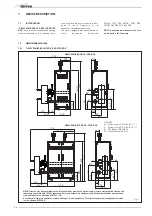
INDOOR INSTALLATION
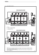
EXHAUST KIT
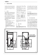
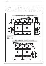
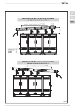
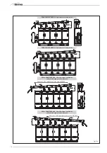
Refer to fig. 6 and 6/a-b for this type of
installation.
The indicated solutions have the exhaust
manifold positioned both on the module’s
right and left and the use of extension cod.
8102522/23, supplied separately, is only
necessary when the hydraulic separator
box/safety kit cod. 8101517 is installed.
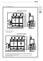
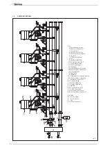
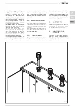
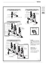
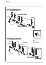
Figure 6/c for 6/d illustrates the elements
included in t he pol ypr opy lene exhaus t
manifold required for single and multiple
module installation, and the available acces-
sories to be used according to installation
type.
NOTE: The kits are purposely treated also
to resist weathering when installed out-
doors.
DEWY EQUIPE 240 BOX - Kit collettore fumi uscita lato dx
DEWY EQUIPE 240 BOX - Kit collettore fumi uscita lato sx
405
Ø 160
H
Fig. 6
H
120-P120 BOX
470
180 BOX
525
240 BOX
525
DEWY EQUIPE 240 BOX - Right side exhaust manifold Kit
DEWY EQUIPE 240 BOX - Left side exhaust manifold Kit
Содержание DEWY EQUIPE 120 BOX
Страница 2: ......
Страница 88: ......
Страница 89: ...TAGLIARE LUNGO LA LINEA TRATTEGGIATA ...
Страница 90: ......
Страница 91: ......

