


S i 5 3 4 1 / 4 0
12
Preliminary Rev. 0.9
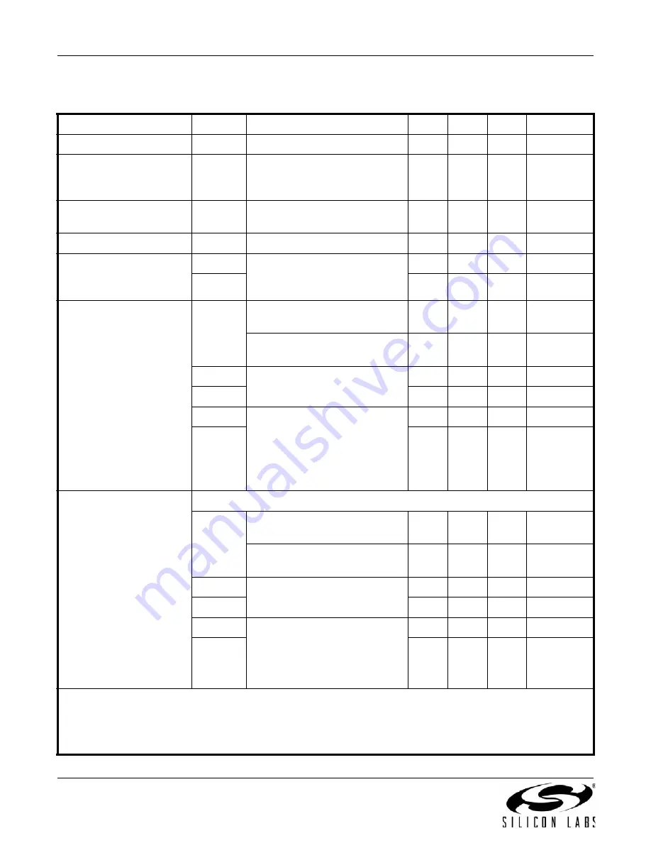
Table 8. Performance Characteristics
(V
DD
= 1.8 V ±5%, V
DDA
= 3.3 V ±5%, T
A
= –40 to 85 °C)
Parameter
Symbol
Test Condition
Min
Typ
Max
Units
PLL Loop Bandwidth
f
BW
—
1.0
—
MHz
Initial Start-Up Time
t
START
Time from power-up to when the
device generates free-running
clocks
—
30
—
ms
POR
to Serial Interface
Ready
t
RDY
—
—
10
ms
PLL Lock Time
t
ACQ
—
—
120
ms
Output delay adjustment
t
DELAY
f
VCO
= 14 GHz
Delay is controlled by the Multi-
Synth
—
0.28
—
ps
t
RANGE
—
±9.14
—
ns
Jitter Generation
Locked to External Clock
J
RMS
Integer Mode
12 kHz to 20 MHz
—
0.115
0.200
ps RMS
Fractional/DCO Mode
12 kHz to 20 MHz
—
0.170
0.400
ps RMS
J
PER
Derived from
integrated phase noise
—
0.140
—
ps pk-pk
J
CC
—
0.250
—
ps pk
J
PER
N = 10,000 cycles
Integer or Fractional Mode
.
Measured in the time domain.
Performance is limited by the
noise floor of the
equipment.
—
7.3
—
ps pk-pk
J
CC
—
8.1
—
ps pk
Jitter Generation
Locked to External XTAL
XTAL Frequency = 48 MHz to 54 MHz
J
RMS
Integer Mode
12 kHz to 20 MHz
—
0.100
0.160
ps RMS
Fractional/DCO Mode
12 kHz to 20 MHz
—
0.140
0.350
ps RMS
J
PER
Derived from
integrated phase noise
—
0.150
—
ps pk-pk
J
CC
—
0.270
—
ps pk
J
PER
N = 10, 000 cycles
Integer or Fractional Mode
.
Measured in the time domain.
Performance is limited by the
noise floor of the equipment.
—
7.3
—
ps pk-pk
J
CC
—
7.8
—
ps pk
Notes:
1.
Jitter generation test conditions in synchronous mode: f
IN
= 100 MHz, f
OUT
= 156.25 MHz LVPECL. Does not include
jitter from PLL input reference.
2.
Integer mode assumes that the output dividers (Nn/Nd) are configured with an integer value.
3.
Fractional and DCO modes assumes that the output dividers (Nn/Nd) are configured with a fractional value.


