


MSA213C-S (BiSS/C)
Interfaces English
MSA213C-S (BiSS/C) · Date 24.05.2022 · Art. No. 90036 · Mod. status 111/22
20
1999 0
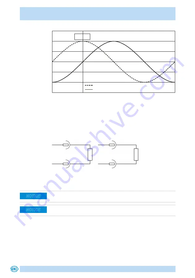
Cos
Sin
Position value
2000-place
In order to ensure interference-free transmission of analog signals, they
are available in the differential form (Sin and /Sin as well as Cos and /Cos)
with a mid voltage of 2.5 V (±100 mV). Difference formation of the signals
results in a signal amplitude of 1 V
PP
(±10 %).
If these signals are not needed, it is recommended to terminate the out-
puts Sin and /Sin as well as Cos and /Cos each with a resistor 120 ...
150 Ohm.
Cos
Sin
/Cos
/Sin
120 ... 150 R
120 ... 150 R
6.2 Digital interface
For dimensioning the downstream electronics, ensure that it is correctly
dimensioned for the set edge distance or counting frequency!
Note that pulses with the widths of the set edge distance may occur with
sensor idleness (due to the internal interpolation procedure).
In parallel with the BiSS C-interface, the LD version outputs speed-pro-
portional incremental signals which have the differential form in accor-
dance with RS422.
The incremental signals are terminated by means of terminating resistors
with 120 ... 150 ohm.
NOTICE
NOTICE
Содержание MSA213C
Страница 26: ...MSA213C S BiSS C 26...
Страница 27: ...MSA213C S BiSS C 27...