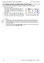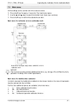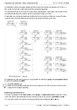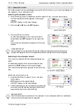
3.1 Front of the controller (controller type K32SK)
Overview and function of the control elements of the controller:
1 - Upper display (red)
- Displays the current reference temperature.
- Displays the individual modes, menu items
and parameters.
2 - Lower display (green)
- Displays the set temperature.
- Displays certain parameters in the individ-
ual modes and menu items.
3 - LED SET
- When flashing, it signals access to the indi-
vidual menu items and parameters.
4 - P key
- Accessing the default set temperature.
- Accessing menu items and parameters.
- Confirming inputs.
5 -
key
- Reducing the setting values.
- Selecting individual menu items.
- Returning to the previous menu level.
6 -
key
- Increasing the setting values.
- Selecting individual menu items.
- Returning to the previous menu level.
7 - U key
Retrieving the saved set temperatures (only for
the S version).
8 - LED OUT 1
Signals the status of the output for the tempera-
ture control:
☼
If the LED OUT 1 lights up, the calibrator /
micro calibration bath is heating.
If the LED OUT 1 does not light up, the cali-
brator / micro calibration bath is not heating.
9a - LED OUT 2
a) Heating instrument
Signals the status of the output for the fan con-
trol:
☼
If the LED OUT 2 lights up, the fan is running
at high speed.
If the LED OUT 2 does not light up, the fan is
running at low speed.
9b - LED OUT 2
b) Heating and cooling instrument
Signals the status of the output for the tempera-
ture control:
☼
If the LED OUT 1 lights up, the calibrator /
micro calibration bath is cooling.
If the LED OUT 1 does not light up, the cali-
brator / micro calibration bath is not cooling.
3.2 Data interface (S versions)
The S version is equipped with a serial communication interface RS485. It is possible to con-
nect a PC, a level converter or a network via this interface.
The utilized software protocol is a MODBUS-RTU protocol, which is used in numerous mar-
ket-available monitoring programs.
The transfer rate (baud rate) is factory set to 9600 baud. Other transfer rates
are available on request.
The 5-pole socket is provided with two connections, A and B, which have to be
connected to the respective sockets of the PC, the level converter or the net-
work.
To enable connection to a PC, the RS 485 signals have to be externally converted into RS
232 or USB signals. Appropriate converters including drivers are optionally available. The PC
5-pole socket


