background image

TP 17 / TP M / TP Multi 

Safety Instructions 

Technical changes reserved 


- 7 - 


Ensure that the complete operating instructions are always available in excellent condi-
tion at the calibrator / micro calibration bath installation site. 


Thermal fuse


For protection purposes, the calibrator / micro calibration bath is equipped with an auto-
nomous thermal fuse, which interrupts the power supply to the heater if the temperature 
exceeds a certain value inside the housing. Once the metal bock / liquid bath has cooled 
down, the calibrator / micro calibration bath has to be returned to SIKA for inspection. 


The calibrator / micro calibration bath has been designed as a measurement and control 
instrument. If the calibrator / micro calibration bath is used for purposes not expressly 
specified in these operating instructions, additional safety measures have to be taken. 


The calibrator / micro calibration bath should 

NOT

 be used in 

explosive atmospheres


without appropriate protection (flammable or explosive atmospheres). 


Do not remove or obliterate nameplates or other markings on the device, as otherwise the 
warranty is rendered null and void. 

Special safety instructions: 

(Further) Warnings that are specifically relevant to individual operating procedures or activi-
ties can be found at the beginning of the relevant sections of this operating manual. 


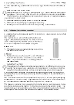
2.1  Safety instructions for the application of calibration liquids 

Calibration liquid water: 


Only use distilled water, otherwise excessive limescale and soiling will build up in the ca-
librator tank. 


Calibration liquid silicone oil: 


Only use distilled water, otherwise excessive limescale and soiling will build up in the cali-
brator tank. 


Always read the safety data sheet supplied with the silicone oil before using it. 


Always ensure adequate ventilation when working with silicone oil, since hazardous sub-
stances can be released. 


Prevent silicone oil from coming into contact with your eyes. 


Since silicone oil is hygroscopic, always use the transport cover to close the calibration 
bath after use. 


IMPORTANT NOTICE! 
The transport cover is equipped with a safety valve, which is activated once the pressure 
reaches approx. 2.5 bar. This can result in hot steam being released. 

 Always unscrew the transport cover before putting the micro calibration bath into ser-

vice, in order to avoid excessive pressure. 

 Wait until the micro calibration bath has cooled down before screwing on the transport 

cover. 


Содержание TP 17 *** M Series

Страница 1: ...info sika net www SIKA net SIKA Ba_TP17 TPM Multi_en pdf 01 2014 Temperature Calibrators Series TP 17 TP M TP Multi Please keep this operating manual for future reference If the device is resold pleas...

Страница 2: ...sioning 16 5 1 Start up procedure 16 5 2 Switching on the calibrator micro calibration bath 17 5 3 Reference and set temperature display 17 5 4 Stabilizing the reference temperature 17 6 Testing tempe...

Страница 3: ...e damage to property CAUTION High temperature This sign indicates dangers resulting from high temperature that can lead to health defects or considerable damage to property CAUTION Material damage Thi...

Страница 4: ...ies TP 17 TP M TP Multi include the following calibrator micro calibration bath types Metal block calibrators Micro calibration baths TP 17 165 c h TP 17 165 S c h TP M 165 S c h TP M 165 S U c h TP 1...

Страница 5: ...repair 1 1 Intended use The calibrators of the series TP 17 TP M TP Multi are only allowed to use for the inspec tion of temperature sensors The operational safety of the supplied instruments is only...

Страница 6: ...n operation and maintenance of the TP 17 TP M TP Multi must hold a relevant qualification This can be based on training or relevant tuition The personnel must be aware of this operating manual and hav...

Страница 7: ...and void Special safety instructions Further Warnings that are specifically relevant to individual operating procedures or activi ties can be found at the beginning of the relevant sections of this op...

Страница 8: ...part of the housing contains the complete electronic unit for controlling the refer ence temperature Solid state relays SSR are used to control the heating and cooling elements A controller with a two...

Страница 9: ...icro calibration bath is not heating 9a LED OUT 2 a Heating instrument Signals the status of the output for the fan con trol If the LED OUT 2 lights up the fan is running at high speed If the LED OUT...

Страница 10: ...1 1 or USB 2 0 A network configuration allows the connec tion of up to 32 calibrators micro calibra tion baths to the same network Certain factory settings have to be carried out to enable configurat...

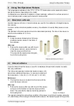
Страница 11: ...ve in the block of the calibrator After use Remove the sleeves after use with the aid of the sleeve remover and remember to clean the sleeve and the block This prevents the sleeves becoming jam med in...

Страница 12: ...ith the aid of the sleeve remover After use Remove the sleeves after use with the aid of the sleeve remover and remember to clean the sleeve and the block This prevents the sleeves becoming jammed in...

Страница 13: ...liquids Use the sleeve changing tool fit the tub insert in the block Just like the tank the tub insert can be closed with the associated cover Both threaded covers are leakproof so the calibration liq...

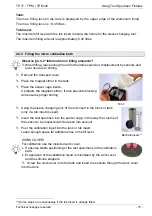
Страница 14: ...before calibration of the sensors Exchange the worn magnet stirrer Exchange dirty smeary calibration fluid 4 4 2 Information on filling amounts CAUTION Risk of incorrect measurement or material damag...

Страница 15: ...cage inside It protects the magnetic stirrer It also prevents blocking and ensures proper stirring Using the sleeve changing tool fit the tub insert in the block or tank only if a tub insert is used I...

Страница 16: ...on sleeves into the tank This will prevent the sleeves becoming jammed in the tank 5 Commissioning Before switching on the calibrator or the first time please follow the instructions in the follow ing...

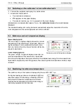
Страница 17: ...the metal block liquid bath When us ing the calibrator micro calibration bath with more than one function then the chosen function will be dis played in alternation Lower display green The green 4 di...

Страница 18: ...he status of the test specimen Remember that the test specimen requires a short period of time until it absorbs the temperature of the metal block or liquid bath The internal references are set to nor...

Страница 19: ...layed by the lower display The LED OUT 1 indicates the status of the output for the heater control If LED OUT 1 lights up the temperature is being increased If LED OUT 1 does not light up the heater i...

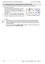
Страница 20: ...is displayed by the lower display Press the key to increase the set temperature Press the key to decrease the set temperature Press the P key again to confirm the new set point NOTES B Press the and...

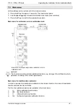
Страница 21: ...Main menu for simple temperature calibrator or micro calibration bath NOTICE The S version provides certain additional functions e g storage of four different set tem peratures or setting of the contr...

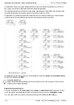
Страница 22: ...n an external reference is used Please connect this to the mini DIN socket and turn the selector switch to ext Ref Menu structure S versions As displayed by the menu structure it is possible to reach...

Страница 23: ...tched off and the reference temperature will continuously change and adjust to the room temperature without having to be further regulated Switching on the automatic control The control is switched of...

Страница 24: ...Press the key to decrease the output capacity PLEASE NOTE Press the and key to raise and lower the value by 0 1 respectively If the keys are held pressed for at least one second the value increases o...

Страница 25: ...ur set point memories SP1 SP2 SP3 and SP4 Press the P key to open the respective set point memory The selected set point memory e g SP 3 flashes on the upper display The corresponding current set temp...

Страница 26: ...ry out a gradient control yourself and thus determine the time in which the set temperature is reached The time can be shorter or longer than the time usually required by the calibrator micro calibrat...

Страница 27: ...in 2 C min 0 5 C min 2 C min 0 5 C min 2 C min 0 5 C min 2 C min 0 5 C min 1 Heating gradient SLor The heating gradient SLor is active if the reference temperature is lower than the set tem perature E...

Страница 28: ...display LED SET flashes on the lower display Press the or key until OPEr appears Press the P key again the group level opens OPEr appears on the upper display SP appears on the lower display and LED...

Страница 29: ...SLor Press the key to decrease the heating gradient SLor Press the and key to raise and lower the value by 0 1 respectively If the keys are held pressed for at least one second the value increases or...

Страница 30: ...y to increase the cooling gradient SLoF Press the key to decrease the cooling gradient SLoF Press the and key to raise and lower the value by 0 1 respectively If the keys are held pressed for at least...

Страница 31: ...tion time ap pears on the lower display Press the key to increase the duration time dur t Press the key to decrease the duration time dur t Press the and key to raise and lower the value by 0 1 respec...

Страница 32: ...is running If the LED OUT 2 does not light up the cooling is not active PLEASE NOTE After switching off or after removing the mains connection the installed fan can no longer provide cooling air Neve...

Страница 33: ...le details what problems you can solve yourself and how to solve them Problem Possible Cause Remedy Interruption of the internal reference sensor or the internal reference sensor is defective uuuu Mea...

Страница 34: ...een made 12 Recalibrating The calibrator micro calibration bath is adjusted and tested with measuring equipment in ac cordance with recognized national standards prior to delivery The calibrator micro...

Страница 35: ...isplay unit C or F optional Two line display Reference temperature Target temperature 4 digit 7 segment LED 7mm high red upper display green lower display Display for sensor break Sensor break behavio...

Страница 36: ...ontrol stability 0 1 C Electrical characteristics Power supply 90 240 VAC 10 50 60 Hz 230 VAC 15 10 50 60 Hz 115 VAC 20 10 optional 50 60 Hz Power consumption 400 VA 600 VA 2000 VA 1000 VA Fuse 90 240...

Страница 37: ...rol stability Dry block 0 05 C Infrared black body 0 05 C Surface temperature 0 2 C Electrical characteristics Power supply 90 240 VAC 10 50 60 Hz 230 VAC 15 10 50 60 Hz 115 VAC 20 10 optional 50 60 H...

Страница 38: ...1 C 0 2 0 2 Emission degree Infrared black body 0 9994 Control stability Dry block 0 05 C Infrared black body 0 05 C Surface temperature 0 2 C Micro calibration bath 0 05 C Electrical Characteristics...

Страница 39: ...middle at a depth of 155 mm TP 17 At full depth the reference sensor is located in the middle of the sleeve Infrared TP 17 166 S TP 17 450 S series TP M S All periods relate to a reference sensor Pt1...

Страница 40: ...Technical data TP 17 TP M TP Multi 40 SIKA Ba_TP17 TPM Multi_en doc 01 2014 14 5 2 TP 17 450 TP 17 650 dry block 14 5 3 TP 17 166 S TP 17 450 S infrared surface...

Страница 41: ...TP 17 TP M TP Multi Technical data Technical changes reserved 41 14 5 4 TP M 165 S Dry block infrared and surface Water and silicone oil...

Страница 42: ...Technical data TP 17 TP M TP Multi 42 SIKA Ba_TP17 TPM Multi_en doc 01 2014 14 5 5 TP M 225 S TP M 255 S Dry block infrared and surface Water and silicone oil...

Страница 43: ...TP 17 TP M TP Multi Technical changes reserved 43...

Страница 44: ...TP 17 TP M TP Multi 44 SIKA Ba_TP17 TPM Multi_en doc 01 2014...

Отзывы: