SIGMATEK MDD 111-1 Скачать руководство пользователя страница 59


MDP 102-1 

29.08.2019 

Page 59 


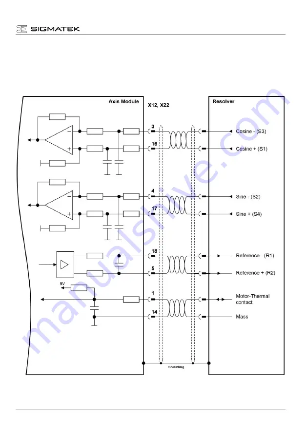
5.5.1  Resolver Feedback 


The standard feedback system for servomotors is resolver feedback. The servo drive allows 
evaluation  of  single  speed  (2-pole)  and  also  multi  speed  resolvers  (up  to  32-pole).  The 
maximum cable length is limited to 50 m. 
If a thermal contact is used in the motor, the signal is also connected via the resolver cable. 


Содержание MDD 111-1

Страница 1: ...e two single axis modules for 230 V and 400 V and two dual axes module for 230 V and 400 V which have a scalable output current range of the 2 axes The supply module and the axes modules are put on a...

Страница 2: ...gear cabinet 26 3 3 1 Connection diagram and pin assignment of power supply module 26 3 3 2 Ground 29 3 3 3 Mechanical construction and mounting 31 3 3 4 Connector properties 33 3 3 5 Wire sizing 33 3...

Страница 3: ...i Motor 65 5 5 6 Panasonic Feedback 66 5 5 7 BiSS C Feedback 67 6 Maintenance 68 6 1 Replace and repair 68 7 Appendix 70 7 1 Transport storage and disposal 70 7 2 Troubleshooting and Fault Elimination...

Страница 4: ...MDP 102 1 Page 4 29 08 2019 1 1 Components of a servo system...

Страница 5: ...face description Setup of the servo drive Accessories Transport storage maintenance disposal Abbreviations used in this manual Abbreviation Meaning AWG American Wire Gauge BGND Earth of 24V help and b...

Страница 6: ...2019 2 2 Symbols used in this manual Danger Shock current Danger to personnel from electricity Caution General General warning see document Caution Hot surface Hot surface more than 80 C 176 F Import...

Страница 7: ...allation setup and maintenance Properly qualified per sons are those who are familiar with the transport assembly installa tion setup and operation of the product The manufacturer of the machine must...

Страница 8: ...ge Caution General The availability of the servo drive system is limited according to EN61800 3 This product can cause radio interference problems in living quarters In this case it may be necessary f...

Страница 9: ...on a mounting plate in the cabinet This is due to the related dissi pated breaking energy in the ballast resistor See technical data of module carrier Check measure the housing and the module rack tem...

Страница 10: ...under supervision of qualified personnel and have been authorized to operate and maintain safety related equipment systems and facilities in com pliance with the strict guidelines and standards of saf...

Страница 11: ...environmental conditions tem perature protection class humidity mains input EMC and the mounting posi tion It must be mounted in a closed switchgear cabinet with minimum IP54 The servo drive has to be...

Страница 12: ...onditions described in this documentation too hot without closed switchgear cabinet wrong mounting position etc Be very careful in plants were conductive material carbon fiber graphite with machining...

Страница 13: ...MDP 102 1 29 08 2019 Page 13 2 6 Nameplate...

Страница 14: ...MDP 102 1 Page 14 29 08 2019 2 7 Block Diagram and Concept Block diagram of the Power Supply Module...

Страница 15: ...Internal Bus Interface Control and Communication Unit Axis Module Module Carrier DC link Internal Bus 24V BR Internal Supply U_Treiber Feedback Converter Res En coder X12 X22 Feedback 2x3 2 x 6 M X11...

Страница 16: ...resistor Auxiliary power supply input for the internal supply Separate power supply input for the holding brake for safety reasons Integrated safety functions Micro controller system with communicatio...

Страница 17: ...nal supply Separate 24 V input for holding brake supply Input EMI filter for AC input 24 V auxiliary supply and holding brake supply for class A industrial environment Safety functionality STO Safe To...

Страница 18: ...nverter and speed controller update time 62 5 s Spline interpolator and position controller update time 62 5 s Full synchronization down to the power stage to the beat of the host controller with cycl...

Страница 19: ...dditional supply voltage 24 V W Max 50 Holding brake supply voltage 24 V BR VDC 23 26 depending on type of selected holding brake Regen Circuit DC Link capacitance F 540 G VMAINS 230 rated mains volta...

Страница 20: ...P1 5 5 ST 3 5 Power Supply X2 Phoenix GMSTB 2 5HCV 9 ST 7 62 VARAN Bus X3 X4 maximum length 100 m RJ 45 Digital Inputs X6 Phoenix FK MCP1 5 12 ST 3 5 Mechanics Height mm 155 Width mm 60 Depth with mod...

Страница 21: ...evel at rated data 1000 to 2500 m above sea level with derating of 1 5 100 m Pollution degree 2 Servo drive enclosure protection class IP 20 Mounting position page 31 Ventilation Forced ventilation by...

Страница 22: ...ID B 4 XX XX B Trig ger diagram Take care that the servo drive and the motor are grounded properly Use uncoated zinc plated mounting plates subplates The servo drive system MDD 100 has a high leakage...

Страница 23: ...se level of the control signals because of the high radiation of the motor cables Use only screened motor and feedback cable with shield connections on both ends The prescribed mounting position is ve...

Страница 24: ...s IP54 as minimum For the 24 V supply use only PELV SELV power supplies Use adequate insulated wire end sleeves External source voltage at the inputs ENABLE_L and ENABLE_H has to be excluded in the ca...

Страница 25: ...ck e g force to the load by hanging load additional measures have to be provided e g double disc spring set brake instead of permanent magnetic excited brake Failure to observe this precaution can res...

Страница 26: ...MDP 102 1 Page 26 29 08 2019 3 3 Planning of the switchgear cabinet 3 3 1 Connection diagram and pin assignment of power supply module...

Страница 27: ...MDP 102 1 29 08 2019 Page 27...

Страница 28: ...MDP 102 1 Page 28 29 08 2019 Connector layout of X1 X2 X3 X4 and X6...

Страница 29: ...MDP 102 1 29 08 2019 Page 29 3 3 2 Ground On the MDD module a mounting bracket is found which serves as stress relief as well as shielding Here the cable shield is connected...

Страница 30: ...MDP 102 1 Page 30 29 08 2019 The entire MDD System is grounded over the module carrier in the control cabinet...

Страница 31: ...31 3 3 3 Mechanical construction and mounting The mechanical dimensions of the servo drive system above are A depends on the selected module carrier 120 mm for MDM 011 180 mm for MDM 021 240 mm for M...

Страница 32: ...be placed with a minimum distance of 10 mm to the module carrier The cable duct above must be placed with a distance of 40 mm to the module carrier This is necessary to get enough air through the hea...

Страница 33: ...5 mm 20 22 AWG Solder or crimp X11 X21 GMSTB2 5HCV 6 ST 7 62 1 2 5 mm 14 16 AWG 0 56 0 79 Nm 5 7 inch lb Ground bolt M5 10 mm 8 AWG 3 5 Nm 31 inch lb 3 3 5 Wire sizing According to EN 60204 for AWG ta...

Страница 34: ...AC mains input L1 L3 Size fuses to the average power needed by the servo drives connected to the circuit Suitable for use on a circuit capable of delivering not more than 5000 rms symmetrical amperes...

Страница 35: ...the protective conductor of 2 5 mm AWG 13 as part of a multi conductor supply cable Use an adequate pull relief If a leakage current sensor is used in the mains supply of the servo drive sys tem a le...

Страница 36: ...that condensation water does not leak into electronic devices in the switchgear cabinet Mount cooling units by which amassed condensation water cannot be sprayed into electronic devices by the fan of...

Страница 37: ...actory building Use only properly sealed switchgear cabinets to avoid condensation by the moist external air Especially during installation or servicing while the machine is run ning with open switchg...

Страница 38: ...and the main supply is engaged later This however is not absolutely necessary The main supply can also be activated with the 24 V auxiliary supply at the same time Since the memory of the servo amplif...

Страница 39: ...t t t Emergency ramp tBRon tBRoff Max 1 sec Speed threshold Brake disable delay time Brake enable delay time t t 24V_BR Min 0 2 sec Min 0 1 sec The figure above shows the processing of the holding bra...

Страница 40: ...62061 For his purpose the servo amplifier has two safe inputs ENABLE_L und ENABLE_H The relay output S1 S2 can be used to provide the status of the safety function It is not safety relevant but can b...

Страница 41: ...1 Block IN The input block IN generates the supply voltage for the AMV block This is formed from the voltage difference between ENABLE_H and ENABLE_L Power is therefore available short ly after the ap...

Страница 42: ...CONTR 02 AMP 01 AMP 02 and TR These blocks form a safe switching power supply which generates the driver voltage for U_Treiber through the transformer TR01 It is ensured that the switching supply cann...

Страница 43: ...e system Low Low When the servo am plifier is supplied with 24 V the inputs are closed after a mini mum delay 0 4 of seconds and a maxi mum of 1 seconds Single channel safe status only when using clas...

Страница 44: ...tage is disabled Shut down after opening the safety circuit If the actual speed reaches 1 of min N NMAX V NMAX or the ramp time exceeds 500 ms the brake is activated and the pre set speed I NCMD is im...

Страница 45: ...ad to severe injuries and damage 4 3 1 Test conditions The total safety circuit must be tested for functionability The function test is performed from the following start condition An operation ready...

Страница 46: ...ENABLE_H this means the other signals that can have a 24 V potential must be wired separately For ENABLE_L this means the other signals that can have Ext GND potential must be wired separately Because...

Страница 47: ...061 an error proof output of a safety PLC must be used There are two Types of error safe outputs 1 A simple error safe output which functions based on Ext GND only This is then connected to the ENABLE...

Страница 48: ...MDP 102 1 Page 48 29 08 2019...

Страница 49: ...MDP 102 1 29 08 2019 Page 49 2 Two channel error proof relay output with which the output is connected to EN ABLE_H and the output to ENABLE_L...

Страница 50: ...MDP 102 1 Page 50 29 08 2019...

Страница 51: ...d mains is not grounded an over voltage protection unit has to be installed in the input of the switchgear cabinet page 36 Note If the DC link of two or more MDD 100 systems are linked with the same s...

Страница 52: ...1 Page 52 29 08 2019 3 phase connection of the MDP 102 1 power supply module Power supply Module 3 5 5 6 6 7 7 4 4 X2 L1 L2 L3 PE PE L3 L2 L1 Direct mains 3 x 115V 10 230V 10 Mains contactor V V V V...

Страница 53: ...e used to supply also the servo drive notice the current rating of the power supply The drive has an additional input for the holding brake supply so that this supply can be switched off independently...

Страница 54: ...Note If the DC link of several servo drives is connected together the mains input must also be connected in parallel to the drives connected of the group Be careful with fusing of the whole system Ple...

Страница 55: ...ard configuration The motor cable length is limited to 25 m If a longer motor cable is required use an addi tion motor choke in the output of the servo drive 6 6 5 5 4 4 3 3 2 2 Motor 1 1 W V U PE B B...

Страница 56: ...re the servo drive is en abled and to be switched off minimal 1ms after disable 6 6 5 5 4 4 3 3 2 2 Motor 1 1 W V U PE B B W W V V U U PE PE B B B B Axis Module X11 X21 2 x REM KEM PE DC DC 24V BR BGN...

Страница 57: ...safe control for the holding brake this requires one or two additional safety contacts in compliance with the safety standards in the 24 V BR line Even in this case a mechanical defect in the holding...

Страница 58: ...thermal contact in the motor winding EnDat encoder single and multiturn Hiperface encoder single and multiturn Sin Cos TTL encoder Sanyo Denki absolute encoder Panasonic encoder BiSS C encoder For En...

Страница 59: ...em for servomotors is resolver feedback The servo drive allows evaluation of single speed 2 pole and also multi speed resolvers up to 32 pole The maximum cable length is limited to 50 m If a thermal c...

Страница 60: ...th EnDat interface The maximum cable length is limited to 10 m If a thermal contact is used in the motor the signal is also connected via the encoder cable 6 19 7 20 23 10 14 1 5V Servo Drive System E...

Страница 61: ...um current Maximum voltage drop 5 V 4 75 V 0 25 V 0 18 mm 0 25 V 0 017 mm m 0 14 A 2 9 4 m Table for EnDat encoder cable lengths Type code description Motor type Encoder Type Encoder Perfor mance Max...

Страница 62: ...length LCable Lwire 2 Legend U Voltage drop 5 V supply minimum encode supply R Wire resistance I Maximum required encoder current rho Specific resistance of the wire 0 017 for copper Lwire Entire wir...

Страница 63: ...for servomotors The maximum cable length is limited to 25 m If a thermal contact is used in the motor the sig nal is also connected via the encoder cable 7 20 6 19 23 10 14 1 5V Servo Drive System HI...

Страница 64: ...dback system used with linear or torque servomo tors The maximum cable length is limited to 10 m If a thermal contact is used in the motor the signal is also connected via the encoder cable The upper...

Страница 65: ...absolute Encoder types PA035C PA035S and RA035C X12 X22 brown blue 22 red black 5V 8 Shielding 120R DATA DATA 14 Pink Purple V BAT 2 Conductor coloring 6 6 5 5 4 4 3 3 2 2 Motor 1 1 W V U PE B B PE D...

Страница 66: ...e 66 29 08 2019 5 5 6 Panasonic Feedback The Panasonic feedback analysis is supported starting with FW version 1 84 in combination with the MDD FPGA version v22 see parameter I HC The maximum cable le...

Страница 67: ...Feedback The BiSS C analysis is supported starting with FW version 1 84 in combination with the MDD FPGA version v22 see parameter I HC The maximum cable length is 10 m If a thermos contact is used t...

Страница 68: ...switchgear cabinet and remove the fuses supplying the servo drive system Wait at least 7 minutes after disconnecting the servo drive system from the mains supply voltage before touching live sections...

Страница 69: ...e it to the disassembled one Install only the same type Plug the connectors Be careful not to swap connectors Install the fuses supplying the servo drive system switch on the main switch of the switch...

Страница 70: ...ace If the packaging is damaged check the unit for visible damage In this case inform the shipper and the manufacturer Do not install and operate the unit in this case Packaging Card box can be recycl...

Страница 71: ...form remove all electrical connections and supply the servo amplifier for about 30 min from 230 VAC single phase on terminals L1 L2 Disposal The servo drives can be reduced to its principal components...

Страница 72: ...cans the bootloader rn Controller is in normal operating mode Er A fatal internal error was detected 7 2 2 LED Indication Each axis module of the MDD100 servo drive system has two LED s for each axis...

Страница 73: ...he motor torque is too low or different in the both direc tions M ROFF is not set to the right value Motor and or feedback con nection is wrong Set M ROFF to the right value Connect motor and feedback...

Страница 74: ...versa 2 Not used 3 DC over voltage internal regen resistor dama ged replace module rack 4 DC under voltage mains supply voltage too low when drive is enabled disable drive before the DC link voltage c...

Страница 75: ...ring of motor or feedback cable High speed overshoot more than 1 2 V NMAX Check M ROFF Check wiring Optimise control loops 15 Following error Following error window P PEMAX too small Increase P PEMAX...

Страница 76: ...t Regen power limit was reached and the regen resistor was switched off 23 Brake supply fault Holding brake supply 24 V BR is not supplied when software enable is set M BRAKE 1 When the motor has a ho...

Страница 77: ...er Limitation When the sum output power of all axes exceeds the power supply limitation Servo drive system meets not the demands of the Application 30 reserved 31 Fan error The fan does not reach the...

Страница 78: ...run outside the control cabinet correct shielding is required This is especially important if due to physical requirements the bus lines must be placed next to sources of strong electromagnetic noise...

Страница 79: ...Component If the Ethernet lines are connected from a VARAN component to a VARAN node outside the control cabinet the shielding should be placed at the entry point to the control cabinet housing All n...

Страница 80: ...onal shield connection is required This requires that only IP67 modules and connectors be used These components are very robust and noise resistant The shielding for all sockets in IP67 modules are in...

Страница 81: ...induce interference in a VARAN bus line Spike voltages are deflected over the metallic housing of a RJ45 connector Noise is conducted through the control cabi net housing without further action from t...

Страница 82: ...ting Noise Generating Components With the connection of power components that generate strong electromagnetic noise it is also critical to ensure correct shielding The shielding should be placed befor...

Страница 83: ...n Two Control Cabinets If two control cabinets must be connected over a VARAN bus it is recommended that the shielding be located at the entry points to both cabinets Noise can thereby be kept from re...

Страница 84: ...MDP 102 1 Page 84 29 08 2019...

Отзывы: