❑
3) Once the cowl fits nicely in place, use pieces of tape to
hold it onto the fuselage. What you want to see is the black stripes
on the cowl lining up with those on the fuselage and that, in side
view, the stripes are straight. The front of the engine should be
nicely centered in the cowl opening. With the cowl held in the
position with tape, mark the cowl mounting screw positions onto
the fuselage through the pre-drilled holes in the cowl. Remove the
cowl and drill pilot holes for the cowl screws at the marks
just made.
At the center of each mounting hole mark, use a
#56 (.046” dia.) bit to drill four pilot holes for the mounting screws.
Use a small Phillips screwdriver to now mount the cowl in place to
the fuselage. We suggest hardening these holes by removing the
screws and using thin CA glue, applied with a small applicator tip,
to place a small drop of glue into each hole. Let the glue set and
again run the mounting screws in place.
❑
4) Now that the cowl mounts nicely in place, the engine
needle valve requires an extension to exit the cowl. This requires
a music wire needle valve extension. Most engines come with
needle valves that have holes in their ends and setscrews in place
for just such extensions. Our Saito needle valve has this feature
with a center hole diameter just large enough to accept 5/64” dia.
(.078) K&S music wire. The idea here is to create a perfect sized
hole for this extension at exactly the correct place in the cowl when
it is in place on the fuselage.
First remove the cowl. Cut a 4" length of 5/64" dia. music wire and
deburr the ends. Insert one end of this wire fully into the hole in
the needle valve and then tighten the setscrew enough to hold it
securely. Thread the needle valve and wire extension fully in place
in the carburetor. Lay a straight edge against the fuselage side at
the nose, intersecting the piece of wire. Mark this point on the wire
with a marker pen. Remove the needle valve from the engine and
remove the wire extension from the needle valve. Cut the wire to
length at the mark just made. Sharpen one end of this wire to a
sharp, tapered point using a Dremel
®
Tool and a carbide cut-off
wheel. Reinstall the unsharpened end of the wire fully back into
the needle valve and tighten the setscrew.
Reinstall the needle valve fully back into the carburetor. Mount the
cowl to the fuselage with the mounting screws. From the front of
the cowl, use a pair of hemostats to begin turning the needle valve
out of the carburetor. As the needle valve is turned, the sharpened
end of the wire will come into contact with the inside surface of the
cowl. Continue turning the needle valve until it is firmly pressed
against the inside cowl surface. Place a pad paper over the cowl
at the location of the sharpened wire point. Using a tap hammer,
lightly tap the paper pad. Removing the pad, you should see a
"dimple" formed on the outside surface of the cowl. When you can
see this mark, remove the cowl from the fuselage. Use a 3/32" dia.
❑
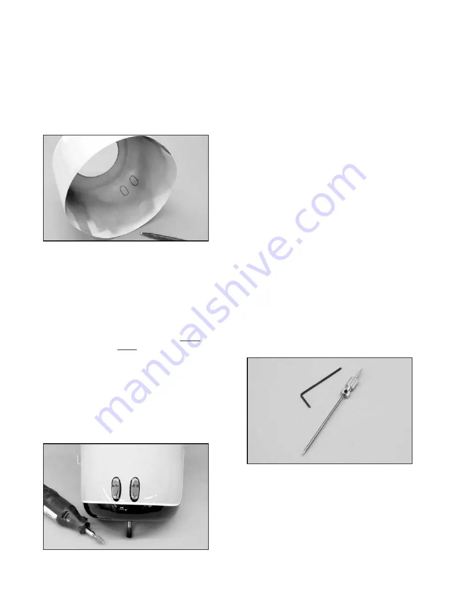
1) With the fuselage sitting upright on your work surface, try
first fitting the cowl over the engine and back onto the fuselage. In
the case of our Saito 1.00, we found that the two valve covers
at the top of the engine head prevented the cowl from fitting
correctly. This meant that the cowling had to be relieved in that
immediate area in order to fit.
Hold the cowl in place on the
fuselage as squarely as possible, with the black trim stripes
aligned on both sides and use a little tape to hold it in this position.
Use a fine tip non-permanent black marker to roughly outline the
shapes of the valve covers onto the inside surface of the cowl.
Remove the cowl and use the marker pen to make these initial
lines more pronounced, smooth and connected.
Now that these marks are clearly visible inside the cowl, they need
to be transferred to the outside surface of the cowl. To do this we
used a small flashlight held inside of the cowl to easily see the
marks on the outside surface through the yellow paint. We again
used a marker pen to trace these lines onto the outside surface of
the cowl. If you don't have a small enough flashlight, use a bare
light bulb - it works great.
❑
2) Using a Dremel
®
Tool with a tapered sanding bit, carefully
create the shaped openings in the cowling at the valve cover marks
just made.
Whenever working with fiberglass, always use a
facemask and safety glasses! Do not get carried away and remove
too much material, just stay within the lines. Now, refit the cowl
over the engine and onto the fuselage. Use the marker pen to now
open and refine the relief marks on the cowl. Remove the cowl and
again use the Dremel
®
Tool and sanding bit to open the holes to the
marks you just made. Continue this process until you have neatly
made the required openings for your engine. The whole idea here
is to "sneak up" on these openings, continually checking your work
with the cowl in place over the fuselage. Work neatly until the cowl
fits nicely, leaving approximately 1/16” - 3/32” clearance all around
these openings.
21


