


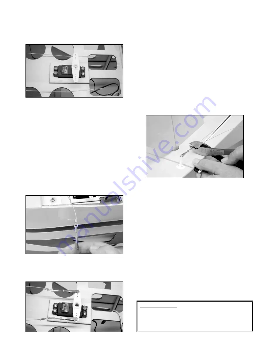
transmitter to correct this. Now fit the rudder output arm onto the
servo, aligning it at 180
O
to the servo body. If it will not fit at the
180
O
position, try reversing it on the output shaft. If necessary,
use the transmitter "Sub Trim" function to achieve the correct
positioning.
With the servo arm now seated correctly and with the servo
moving in the correct direction, the pull-pull cables are now
attached to each side of the output arm.
c) Remove one of the taped cable ends from the servo tray.
Slide a copper swage onto the cable end, holding it with your
fingers and then thread the end of the cable through the small hole
in one of the rigging couplers. Loop the end of the cable back
through the copper swage.
Leaving about 1/2” of cable end
exposed at the copper swage, firmly bend the cable end at right
angles to the swage.
Now pull the cable through the swage,
closing the loop with the rigging cable to within about 3/8" or so
away from the swage. Use a crimping tool or a pair of needle nose
pliers to firmly crimp the swage at its middle, securing the cable
loop.
Use wire cutters to remove the excess exposed cable
(earlier bent at 90
O
) at the swage, leaving about 1/16" or so.
Repeat this process with the remaining cable for the opposite side
of the output arm.
Install the clevis ends of the two rigging couplers onto the correct
sides of the output arm, one in each outermost end and install and
tighten the output arm screw into the rudder servo. Turn off the
receiver and transmitter for now.
15
❑
14) The final pull-pull rudder connections are now made at the
two rudder control horns. Use a piece of masking tape at the
leading edge of the fin and rudder to hold the rudder in neutral to
the fin. Turn the radio system on and turn the fuselage over, upside
down on your work surface.
Center the metal R/C links on both threaded pull-pull fittings,
leaving equal amounts of adjustment in either direction and tighten
the knurled nut firmly against the clevis. Slide a brass swage tube
onto one of the pull-pull cable ends. Thread the end of the cable
end through the small hole in the rigging fitting and then thread the
cable end back through the copper swage tube.
Connect the
clevis to the outermost hole in the corresponding nylon control
horn. Pull the loose end of the cable taut and slide the swage tube
back toward the pull-pull fitting, to within about 3/8” or so. Test the
cable with finger pressure. The idea is to set the cable straight,
without being too tight. Use a crimping tool or needle nose pliers
to firmly crimp the swage tube at its center. Repeat this same
procedure with the opposite pull-pull cable.
Remove the piece of tape holding the rudder to the fin. Check the
rudder's position with the fin - it should be in neutral. If not, adjust
the metal clevises as needed to set the rudder at neutral. Test
the action of the rudder with your transmitter - it should move
smoothly.
With the fittings now adjusted and set, tighten the
knurled nuts on each of the pull-pull fittings firmly against the metal
clevises.
Bend the excess cable in front of both swage tubes
firmly to 90
O
and trim off the excess cable using wire cutters,
leaving a 1/16" or so.
Turn off the receiver and then the
transmitter and disconnect the rudder servo cable from the
receiver.
As recommended with all clevis-to-control horn connections, short
lengths of silicon fuel tubing should be placed onto each clevis as
a retainer.
ENGINE AND FUEL TANK INSTALLATION:
The following steps will show the installation of a Saito 1.00
four-stroke engine, mounted in the inverted position. To make the
initial fitting of the engine to the mounts more convenient, remove
the muffler, header pipe, and needle valve for now.
IMPORTANT NOTE:
The motor mounts provided with the
Waco SRE ARF kit are of excellent quality and designed to
work well with 2-stroke engines up to 1.20 displacement and
4-stroke engines up to 1.50 displacement. DO NOT use any
engine larger than these with the supplied motor mounts. DO