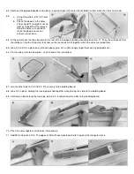
SIG Kougar MARK II SIGRC35 Скачать руководство пользователя страница 16

77.

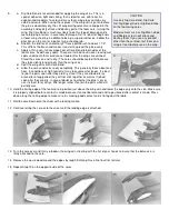
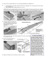
a. Cover the holes in the blind nuts 

on the back of the firewall with 
small pieces of tape to prevent 
glue from oozing into the 
threads. (Look ahead to Picture 
No. 80.)  

b. Epoxy the block and firewall to 

the fuselage.  

c. Shape and sand the block to the 

contour formed by the firewall 
and F-2. 

 
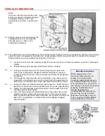
Assemble the tank for use during Steps 78 and 79.


TIPS ON TANKS

 
IMPORTANT: To prevent fuel spray from staining the canopy, run the tank vent line 
out of the bottom of the cowling. Fill the tank through the muffler pressure line or 
needle valve line.

We occasionally receive suggestions from builders that a removable hatch be designed into the model for access to the gas 
tank. Our opinion is this is not the best method in most cases. The hatch opening makes the nose weaker and there is no 
good way to keep oil leaking in around the hatch. A method of fastening has to be built into the fuselage to hold a hatch in 
place.

Modern plastic tanks are virtually indestructable under normal use and bursting or 
cracking is almost unknown. If you use Sig Heat Proof Silicone tubing (which will 
not harden or deteriorate in fuel) in the plastic tank, the tank will seldom have to be 
removed. We have models in which tank has been installed for three or four years 
without ever needing removal. So it is quite practical to put the tank in semi-
permanently. Check the models at a contest - you'll find that the majority have 
sealed noses, as does this kit.

Read this before you drill the 7/8" hole in the firewall.


Some fliers prefer not to bring the tank cap through the firewall as is shown in the construction sequence in these instructions. 
Instead they drill two holes for the vent tubes only and make the vent tubes long enough to extend through the firewall. This 
method requires little sealing but it is more difficult to install and remove the tank. The best way to manage this is to feed long 
pieces of fuel line through the holes and attach them to the tank in the cabin area. Steer the tank into the nose as the tubes 
are pulled back through the holes. If you are undecided as to which method you should use, our advice is that large hole 
installation shown in the construction pictures is the best for beginners.

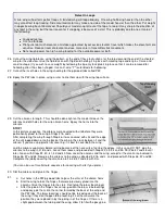
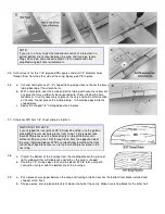
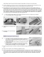
Put scrap wood supports under and at the back of the tank. The front is supported by the 1/4" hole in the firewall. Seal the 
tank cap in the hole with G.E. Silicone Bathtub Seal (available at hardware stores) or Devcon Seal-It. Put an oil-proof finish on 
the firewall and in the hole before sealing the tank cap. Get some of the sealer on the sides of the hole and also put a bead 
over the edge of the cap at the front. Should you need to remove the tank, break out the scrap wood supports in the rear and 
push out the silicon rubber seal around the front cap. Reach into the fuselage and guide the tank outside.

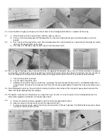
Some builders, after putting their receiver battery in a plastic sack, taping it shut, 
wrapping it in a foam rubber package and stuffing it into the nose under the tank, 
then stuff paper toweling or foam rubber in to fill the nose compartment and keep 
everything firmly in place. 
After installation, put fuel tubing on the vent tube and run it to the outside of the 
cowling on the bottom, so that fuel overflow is not blown over the wing-fuselage 
joint, where it may leak into the fuselage. The best way to fill the tank is to take off 
the fuel line to the needle vlave and pump the fuel in there until it runs out the vent. 
Be sure and use a filter on your fuel supply can, and it is a good idea to have a filter 
between the tank and the needle valve also.
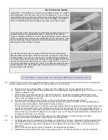
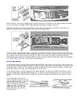
Pressure Feed


If the engine you are using is equipped with a muffler pressure tap, make use of it for a more even fuel feed and reliable 
operation. The hookup for pressure feed is shown in the picture. To fill the tank, remove the fuel line from the engine and 
pump the fuel in. When the tank is full, it will overflow through the muffler pressure line. Use transparent or translucent fuel 
line so you can see the fuel starting to overflow when the tank is full. Should some fuel happen to get in the muffler, drain it 
out before starting the engine. Do not try to fill the tank in reverse from the pressure line, the tank will not fill properly and fuel 
may be forced into the engine.

Содержание Kougar MARK II SIGRC35

Страница 1: ...ain as high an average quality as used to be the case and this situation is getting worse Every piece of balsa supplied cannot be 100 perfect or kit prices would have to be greatly increased Mineral stains or small knots do not seriously affect wood strength Even with the very best grades of balsa there is a natural tendency for some sticks or sheets to immediately bow upon being cut off from a pe...

Страница 2: ...You can switch to 100 grit followed by 220 silicone paper for final finish just before covering In addition to the large block there are places where a smaller one is handy Also a sandpaper file can be made by gluing sandpaper to a flat spruce stick for working tight places We have an especially handy extra long sanding block made from a 40 inch piece of aluminum channel with sandpaper glued to it...

Страница 3: ...e center joint If there is any mismatch in the airfoil shape sand as required to make them fit smoothly together Done this way little matching will be required after planking THE SECRET OF A PERFECT FOAM WING It s a simple matter of a FLAT table Most tables are not flat as can be seen by checking them with a good straightedge If a foam core is covered on a bowed or twisted surface then the wing wi...

Страница 4: ...erally takes about one hour In conditions of high humidity it may take somewhat longer It is best to join the parts soon after they are dry since if they are allowed to lay around for a long period they will not stick together as well as if joined soon after they are dry In case of doubt as to whether the glue is dry or not it is best to let it dry a little longer rather than join the parts while ...

Страница 5: ...own the center of the leading edge from root to tip will help get the shape true all along the wing 23 a Epoxy glue the anchor block to the grooved block b Cut out the balsa sheeting above the landing gear block slots in the foam core The slots may be located by pressing on the sheeting or by use of the waste block from the foam core Cut the holes in the sheeting out undersize at first so that the...

Страница 6: ...ximately correct dihedral angle To check it set up the wing halves as shown in the drawing below with each wing tip blocked up 1 Sand the wing ends Photo 25 as required to make the cente joint fit correctly together Glue the halves together with Sig Epoxy Glue or Sig Kwik Set Glue Use plenty of glue where the balsa shee meets so that the joint between the two halves is completely filled Be certain...

Страница 7: ...ron horns Epoxy the horns into the ailerons STOP In this picture sequence the ailerons were covered with silk before they were permanently glued to the wing in Steps 31b and c After completing the wing through Step 46 it was covered with silk and the edge of the silk lapped down onto the back of the wing in the crack between it and the aileron If you are using plastic film covering it is best to c...

Страница 8: ...y sand as required to make it fit b Hold the wing in position and mark the dowel holes in the wing by punching through the holes in F 2 with a 1 4 drill a piece of tubing or a rod c Drill the holes in the wing out oversize about 9 32 diameter to allow some wiggle room during the final positioning and gluing in of the dowels Dig out a little foam just behind the leading edge so the glue will form a...

Страница 9: ...d 1 4 trailing edge stock in place 37 Cut pieces WS from 1 8 sheet and glue in place SIMPLIFICATION NOTE If you skipped the inset pieces PB in Steps 35 and 36 use the pattern called WSS to cut substitute pieces from scrap 1 16 plywood Glue these WSS pieces over the holes directly on top of the balsa skin without cutting any inset Drill through them from the opposite side of the wing If plywood pie...

Страница 10: ...lue But work quickly for the glue will set up much faster than normally when warmed a Coat the wing center with glue b Lay the tape on top of the glue c Holding one end of the tape so it won t slip squeegee the glue through the tape with a small paddle made from a scrap of balsa Scrape over the tape several times with the squeegee paddle to smooth the tape and remove excess glue 44 Glue hardwood m...

Страница 11: ... mounts b Drill through the mounting holes with a long drill bit If you do not have a long drill bit a length of music wire with a notch filed in the end will do the same thing Or start the holes using a tap holder for a drill bit as shown Motor Mounting Notes When tapping holes in the aluminum motor mounts use kerosene or a specialized aluminum tapping lubricant such as Tapmatic Fluid rather than...

Страница 12: ... the aluminum Use kerosene or a special aluminum tapping lubricant If you do not have a tap drill holes through the mounts and use bolts lock washers and nuts 52 Sand off the rear ends of the fuselage printed sheets 53 Glue the fuselage end pieces FX F2 and FY F2 to the end of the fuselage sheet Use a ruler to make sure the top line where the stabilizer will be mounted is straight Mark the thrust ...

Страница 13: ...n warp Put some heavy weights on the doublers and leave them overnight if possible Some builders prefer contact cement to install doublers The main consideration here is to prepare guides beforehand with pins placed so they will steer the doubler onto the exact required spot for once the glue on each surface makes contact the doubler cannot be moved Another aid makes contact the doubler cannot be ...

Страница 14: ...triangular stock now so the rear ends will fit together when the sides are joined later 65 Glue F 2 and F 3 in place on a side with epoxy glue Use a 900 triangle to get them exactly perpendicular 66 Pin the side on the top view plan see the end of the instructions 67 Join the other side to F 2 and F 3 Pin securely to the building board 68 Glue F 4 in place holding the fuselage pinched together whi...

Страница 15: ...e until it has been used for Steps 32 33 and 34 on the wing OIL PROOF YOUR MODEL One of the most destructive things that can happen to a model is allowing engine oil to soak into bare untreated balsa or plywood It will cause glue joints to loosen and results in a steady increase in weight An oil soaked model cannot be properly repaired or re painted after a crackup since glue and finish will not h...

Страница 16: ...k through the holes If you are undecided as to which method you should use our advice is that large hole installation shown in the construction pictures is the best for beginners Put scrap wood supports under and at the back of the tank The front is supported by the 1 4 hole in the firewall Seal the tank cap in the hole with G E Silicone Bathtub Seal available at hardware stores or Devcon Seal It ...

Страница 17: ...c b Cut a top triangular brace to fit and epoxy in place 81 Sand the top of the fuselage level and smooth 82 Glue pieces of 1 8 sheet to the top of the fuselage STOP At this point you will need the tail parts 83 a Fit the plastic turtle deck and canopy to the fuselage The canopy must be trimmed down as required along the bottom to fit down snugly on the plastic turtle deck Temporarily tape the tai...

Страница 18: ...in the controls first After they are set up attach the controls to the tail surfaces Read INSTALLING EASY HINGES mentioned earlier 89 a Put the wing on the fuselage and check to see if the stabilizer lines up with it when pinned in place on the fuselage If it does not sand one side or the other of the fuselage so that the stabilizer is level b Glue the stabilizer to the fuselage Use epoxy To insur...

Страница 19: ...e covering is completed Models with silk and dope covering have a hard enough shell on the wood so that plywood reinforcement of the control horn area has not been found necessary Other types of covering call for reinforcement by insetting a scrap plywood scab into the surface on the opposite side from the horn This will keep the horn from pulling out of the wood when subjected to unusual strain 9...

Страница 20: ...cks together and takes a lot of pulling and smoothing to get it in place so we do it a bit differently as shown in the photo Pin the dry covering in place and paint the water on with a brush Go around the edges pulling out wrinkles and stretching the material smooth You need not pull it up drum tight in fact going to this extreme is not advisable Just pull out all of the wrinkles Use pins if neces...

Страница 21: ...en you put on a number of coats The rest of the fuselage will not show this effect to any extent because it is four sided and cannot distort The effect isn t noticable until after full cure of the dope and aging which may take several months To prevent this from happening give the inside fuselage a coat of dope every time you give the outside a coat This has an added advantage in making the cabin ...

Страница 22: ...d over decals to increase durability but test them before applying Leave about 1 16 of clear top coat around the decal stars when cutting them out of the sheet Round corners to prevent tearing 96 Assemble the tank hardware as shown in the photo Two vent pipes are used when your engine is equipped with a pressure tap Run a line from one to the muffler tap Put a piece of tubing on the other running ...

Страница 23: ...iner works okay for hooking the wooden push rods to the servo unless the movement or pushrod angle chosen makes it bump into the center post of the servo at the extreme end of the movement This can be fixed by changing the angle of approach to the servo or using a longer arm to bring the retainer out farther away from the center post of the servo This retainer is very easy to attach and detach Du ...

Страница 24: ...e cut with a good pair of side cutting pliers filed in two ground through on the edge of a grinding tool or cut with a silicon cutting wheel on a motor tool RADIO EQUIPMENT INSTALLATION The most convenient method of installing servos is on the plastic mounts which most radio equipment makers offer with their outfits or as an accessory These are screwed to hardwood mounting rails for fuselage servo...

Страница 25: ...r balance Control Movemants Various brands of servos can give different control movement direction and amounts of travel For this reason follow the measurements below when setting the Kougar up for flight rather than any particular horn hole drawn in this book or visible in a Kougar picture Shift the RC link to whatever horn hole will produce the amount of movement shown in the drawings below Meas...

Страница 26: ...painted Add lead to the nose if necessary to get the model to hang level Be sure and fasten the weight securely Do not attempt flight tail heavy The Test Flying position is on the nose heavy side When slightly nose heavy the model is more stable and less likely to stall or snap roll from over elevating It also cuts down reaction of the model to control movements and this is good during test and pr...

Страница 27: ...d with the nose slightly up in a spear throwing motion It is not necessary to achieve a lot of velocity in the launch it is more important that it be released smoothly and with the wings level The model may dip slightly and then should begin climbing at a slight angle If it does not begin to climb after about fifty feet of flight apply a small amount of up to lift the nose Use hand launching only ...

Страница 28: ... ...

Страница 29: ... ...

Страница 30: ... ...

Страница 31: ... ...

Страница 32: ... ...

Страница 33: ... ...

Страница 34: ... ...

Страница 35: ...LIABILITY In use of our products Sig Mfg Co s only obligation shall be to replace such quantity of the product proven to be defective User shall determine the suitability of the product for his or her intended use and shall assume all risk and liability in connection therewith ...

Отзывы: