SIG Four-Star 40 SIGRC44 Скачать руководство пользователя страница 20


The nylon aileron connectors can be 
moved up or down the torque rods to 
adjust the amount of aileron throw. 
Tape the servo wire to the wing to keep 
it from getting tangled with the aileron 
servo, as well as the servos in the 
fuselage.

 
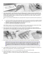
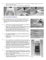
A typical radio installation is shown in the photo above. The receiver and battery on this model are wrapped in foam rubber 
and positioned just forward of the servos. A scrap balsa stick keeps them from moving around during flight. If you use a 
lightweight engine, you may need to install the battery under the fuel tank to achieve proper balance. Notice that the 
aileron connector wire and the charging jack are left accessable, but are tucked away enough so that they can't interfere 
with the servo arms and linkages. The antenna has been routed away from all other wiring and out the fuselage bottom.
 

Pre-Flight Checkout

 
Be certain to range check your radio equipment according to the manufacturer's instructions before attempting test flights. 
A lot of problems can also be avoided if your engine has been well broken-in and the idle adjustments perfected on a test 
stand or in another airplane before installation in the new model.
 
Before flying, you should adjust all of your push rod linkages so that the control surfaces are in their neutral position when 
the transmitter sticks and trim levers are centered. Use the die-cut Lite-Ply Aileron Positioning Guide to set the ailerons in 
neutral, as shown on the plans. When you get to the field, don't be surprised if the elevator and rudder are suddenly 
misaligned. Temperature and humidity changes can cause the nylon push rod tubes to expand or contract slightly. Use the 
trim levers on the transmitter to reneutralize the control surfaces, and do the final trimming in the air. 
 
The control surface movements listed are recommended for the first flight of your FOUR-STAR 40. These movements will 
provide the model with a fair degree of aerobatic capability if it's balanced correctly. Test flights may indicate a need for 
slightly more or less movement, depending on individual model performance and personal preference.
 
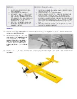
For first flights, make certain that the 
model balances somewhere on the 
main spar. If it balances further back, 
add weight to the nose as necessary. 
Trying to fly with the balance point too 
far aft is much more dangerous than the 
slight increase in wing loading caused 
by adding lead to the nose. Always 
balance the model with an empty fuel 
tank.

RECOMMENDED CONTROL SURFACE MOVEMENTS

For test flying, the following are suggested:

ELEVATOR

1/2" UP and 1/2" DOWN

RUDDER

1" LEFT and 1" RIGHT

AILERON

5/8" UP and 1/2" DOWN


FLYING

 
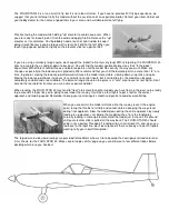
Like it said in the first paragraph of these instructions, the FOUR-STAR 40 was 
designed with flight performance as one of its top priorities - and we weren't 
disappointed! It's a very maneuverable and aerobatic model, but it still slows 
down for soft, gentle landings. It can be flown off pavement or grass, and it 
handles the wind well for such a light model.


Содержание Four-Star 40 SIGRC44

Страница 1: ......

Страница 2: ...on the fuselage instead of the wing simplifies wing construction and lowers the parts count The tailwheel is a bit unique in that it s attached directly to the rudder without the usual plastic tailwheel bearing We ve tested this installation quite extensively without any problems The amazing strength of EASY HINGES and cyanoacrylate adhesive make this simple effective tailwheel installation possib...

Страница 3: ... in contact and positioned correctly before glue application This feature is useful when laminating large sheeted areas like a fuselage side and a fuselage doubler Sig Kwik Shot Accelerator Spraying accelerator on CA any thickness will cure it almost instantly Although CA is fast it s sometimes nice to speed it up even more Debonder This can be used to separate parts but you ll probably use it for...

Страница 4: ...lable Plan ahead Read the book completely and study the full size plans before beginning construction Refer to The Basics of Radio Control In addition to the instruction booklet you are reading now the booklet The Basics of Radio Control has been included with this kit as a reference for installing the engine fuel tank and radio in the FOUR STAR 40 It also contains very important information on pr...

Страница 5: ...ottle pushrod 4 2 56x10 Threaded Rods 2 ailerons l elevator l rudder 15 Easy Hinges Notes Before Beginning Construction Any references to right or left refers to your right or left as if you were seated in the cockpit To build good flying models you need a good straight building board Crooked models don t fly well The building board can be a table a workbench a reject door core from the lumber yar...

Страница 6: ...ng ribs to the spars and trailing edge sheeting b Place scraps of 1 16 balsa near the main spar to accurately space the W 1 wing ribs up from the building board The spacing is required for the center sheeting to be added later c Use the dihedral guage side of the die cut Dual Tool to set the root W 1 rib at the proper dihedral angle before gluing it in place Add the two remaining W 1 ribs 3 a Glue...

Страница 7: ... step Otherwise you may find it difficulf to remove your wing from the board later 6 Pieces for the top center sheeting should be cut from the 1 16 x3 x30 balsa provided in the kit Again Sig Bond is recommended for the front and rear edges of the sheeting to make it easier to sand the joints smooth Also use Sig Bond on the center W 1 rib The sheeting can be glued to the ribs on each end using CA 7...

Страница 8: ...own in the photo Using a modeling knife carefully cut out the outlined area This step accomplishes two things First it clears an area for the aileron servo and second it provides an open area between the main wing spars for the dihedral brace 14 Repeat steps 1 through 13 to build the opposite wing half Joining The Wing Panels 15 a Trial fit the two wing halves with the dihedral brace installed bet...

Страница 9: ...ue in the brass bearings The outer end of the bearings should be even with the outer end of the blocks 18 a Glue the torque rod block assemblies in place on the wing T E again being very careful not to get any glue in the bearings b Notch the balsa trailing edge just forward of the notches in the torque rod blocks to allow full movement of the torque rods c Sand the top of the basswood blocks to m...

Страница 10: ...A will help fill in the weave of the fiberglass resulting in a smoother surface Rub the second coat with your finger protected with plastic wrap keep it moving to smooth out the glue Use a fan to keep the CA fumes away from your face 4 When dry sand lightly to remove any rough spots Try not to sand into the fiberglass tape itself Ailerons 23 Sand the trailing edge of the aileron round and bevel th...

Страница 11: ... the engine mounts To avoid any conflict drill a 1 4 dia relief partially through the back of the mounts at each hole 28 Position your engine on the mounts far enough forward for the propeller to clear the fuselage cheeks and mark the engine mounting holes Remove the mounts then drill at the marks with a bit that s just large enough to clear your engine mounting bolts When the time comes to fasten...

Страница 12: ...he correct angle 35 a Glue the three 3 16 x1 4 x18 balsa fuselage stringers in place b When dry trim off the front of the stringers flush with the front of HR 36 a Bevel the top edge of the fuselage sides with a sanding block to provide a firm seat for the fuselage top deck when it is installed Notice that the angle between the top deck and the fuselage sides varies along the entire length Don t w...

Страница 13: ...to the wing dowel and W 1 wing ribs by working through the opening in the bottom of the wing Be careful not to allow the glue to run down and bond the dowel to F 2 e When dry remove the wing and fill any gaps around the dowel with another application of glue 42 a The 1 4 x3 4 x1 basswood wing hold down blocks key into the notches in the fuselage doubler To accurately fit them temporarily tape or p...

Страница 14: ...e outside of the fuselage b Install the die cut Lite Ply stab support so that it is flush with the top of the fuselage sides c When dry sand the Tee Lock tabs on the stab support flush with the fuselage sides 48 a The nylon pushrods must be supported at each former to keep them from flexing under load Use the die cut Lite ply pushrod straps F 3S and F 4S to support the pushrods Notice that the pus...

Страница 15: ...both of them at the tips until they match perfectly The tips can be left square or sanded round if you prefer 55 a Sand the pre cut 3 16 balsa fin leading edge round b Sand the trailing edge of the pre cut 3 16 balsa rudder round c Draw a hinge line centered on the leading edge of the rudder Bevel the L E using the hinge line as a guide d Sand a notch in the rudder leading edge to clear the elevat...

Страница 16: ...n the wingtips run the covering material around the corner about 1 8 Later when the main top and bottom covering pieces are applied they will overlap the wingtip covering and can be trimmed at the wingtip corners leaving a virtually invisible seam Extend the covering material about 1 8 past the outside edges of the hold down plates again to provide an area for overlap Cover the main portion of the...

Страница 17: ...58 Using a No 11 X Acto blade or similar cut slots approximately 1 2 in depth and slightly wider than the hinges Cut eight slots in the stabilizer and eight matching slots in the elevators at the locations shown on the plans 59 After all of the slots have been cut insert EASY HINGES halfway into the stabilizer slots DO NOT GLUE THE HINGES YET Next carefully slide the elevators onto the hinges You ...

Страница 18: ...e the stabilizer to the fuselage using Kwik Set epoxy Recheck its alignment and adjust as necessary before the glue dries 66 a Cut away a 3 16 wide strip of material from the center of the stabilizer where the fin is to be glued Epoxy the fin to the top of the stabilizer using a triangle to check its alignment as it dries Make certain that the back edge of the fin is lined up with the back edge of...

Страница 19: ...nded that you go through the Pre Flight Checklist in Chapter 7 carefully before attempting to fly Engine And Fuel Tank Installation Engine installation on the FOUR STAR 40 is simply a matter of bolting the engine mounts that were prepared in step 28 to F 1 then bolting your engine to the mounts Finish installing the throttle cable which was partially prepared in step 51 by soldering the connector ...

Страница 20: ...ioning Guide to set the ailerons in neutral as shown on the plans When you get to the field don t be surprised if the elevator and rudder are suddenly misaligned Temperature and humidity changes can cause the nylon push rod tubes to expand or contract slightly Use the trim levers on the transmitter to reneutralize the control surfaces and do the final trimming in the air The control surface moveme...

Страница 21: ... back increases its sensitivity to control inputs but if carried too far the model can become completely unstable and uncontrollable The balance range shown on the plans is a safe area to use for test flights Don t exceed the rearward limit unless you are a very experienced pilot When landing the FOUR STAR 40 may tend to float a bit more than other models you have flown in the past so be ready to ...

Страница 22: ...pm Central Copyright SIG Mfg Co Inc SIG MFG CO INC Montezuma Iowa 50171 0520 LIMIT OF LIABILITY In use of our products Sig Mfg Co s only obligation shall be to replace such quantity of the product proven to be defective User shall determine the suitability of the product for his or her intended use and shall assume all risk and liability in connection therewith ...

Отзывы: