


.
44.
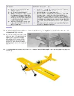
a. Remove the wing and tap the wing hold-down blocks with a 1/4-20 tap. You can apply a few drops of thin CA to the
holes to strengthen the threads.
b. Redrill the holes in the wing with a 1/4" drill bit to pass the nylon wing bolts.
Servo And Pushrod Installation
45.
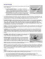
Now is a good time to plan your servo installation. Refer to Chapter 2 of "The
Basics of Radio Control", and the plans for information on where and how to
mount the servos in the fuselage. It's important to have the servos in position so
that the nylon pushrods can be routed properly, with the least amount of
curvature.
46.
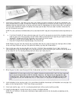
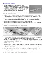
a. Locate the two .190 o.d.x24" nylon outer pushrod tubes, and roughen the
last 3" of each with sandpaper to aid glue adhesion.
b. Slide the outer push rod tubes forward through the pushrod exit slots in the
fuselge sides and the notches in F-6. Continue sliding the tubes until only
about an inch of the roughened end sticks out of the slots.
c. The outer pushrod tubes should meet (but not cross) at the notch in F-5.
Glue a scrap of balsa above the tubes to hold them in place.
d. Apply glue liberally (either slow CA or epoxy) to the outer tubes at the
pushrod exit slots, from both the inside and the outside of the fuselage.
47.
a. Use a single-edge razor blade to trim the outer pushrod tubing flush with
the outside of the fuselage.
b. Install the die-cut Lite-Ply stab support so that it is flush with the top of the
fuselage sides.
c. When dry, sand the "Tee-Lock" tabs on the stab support flush with the
fuselage sides.
48.
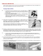
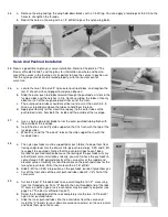
a. The nylon pushrods must be supported at each former to keep them from
flexing under load. Use the die-cut Lite-ply pushrod straps, F-3S and F-4S,
to support the pushrods. Notice that the pushrod straps haven't been
marked for pushrod location because the routing of the pushrods will vary
with different servo installations. Ideally, you want to have the pushrods to
come through F-3S pointed directly at the servo arms of the rudder and
elevator servos. Carefully mark drill locations on the pushrod straps for the
two nylon pushrods. Drill at the marks with a 3/16" drill bit.
b. Slide F-4S then F-3S into position on the pushrods, but don't glue them yet.
c. Cut off the front ends of the outer pushrod tubes about 2-1/2" short of the
servo arms
49.
a. Cut two 2-56x10" threaded rods to an overall length of 2-1/2", measuring
from the threaded end. Put a "Z" bend in the non-threaded end of the rods.
Of course, another type of servo connector may be used if you prefer (see
page 7 of "The Basics of Radio Control").
b. Screw the threaded end of the rods completely into the two .130"o.d.x30"
nylon inner pushrod tubes.
c. Slide the inner pushrod tubes into the outer tubes from the servo end.
Install the "Z" bends (or your alternate servo connectors) on the servo arms
and hook them up to the servos.
Содержание Four-Star 40 SIGRC44
Страница 1: ......