


.
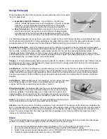
FUSELAGE CONSTRUCTION
Before starting fuselage construction, there are a few subassemblies that should be built and set aside until needed. This is
done to avoid interruptions during the flow of fuselage construction.
Fuselage Subassemblies
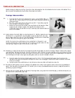
26.
a. Glue together the two die-cut plywood F-1 pieces using KwikSet Epoxy or
slow CA. Use a heavy weight of some kind to hold the two pieces perfectly
flat while drying.
b. Mark the vertical centerline and thrust line on the F-1 assembly using the
cross-section on the plan as a guide.
c. Determine the spacing that will be necessary between the two glass filled
engine mounts to fit your engine, then position the mounts on F-1
accordingly. Mark the location of the four mounting holes and drill them out
with a 3/16" drill bit.
27.
Lightly hammer four 6-32 blind nuts into the back of F-1. Bolt the engine mounts to
the front of F-1 using 6-32x3/4" mounting bolts to align the blind nuts (see note
below). Apply medium or slow CA around the edges of the blind nuts to hold them
in place. Be careful not to get any glue in the threads.
NOTE: The shank of the 6-32 blind nuts may extend too far through F-1 and
interfere with the back of the engine mounts. To avoid any conflict, drill a 1/4" dia.
relief partially through the back of the mounts at each hole.
28.
Position your engine on the mounts far enough forward for the propeller to clear the fuselage "cheeks" and mark the engine
mounting holes. Remove the mounts, then drill at the marks with a bit that's just large enough to clear your engine mounting
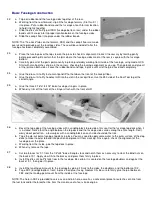
bolts. When the time comes to fasten the engine to the mounts, use 3/4" long bolts (4-40 or 6-32, depending on the engine)
and matching aircraft lock nuts (engine mounting bolts and nuts are not included in the kit).
29.
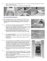
a. Carefully center the aluminum landing gear over the 1/4"x1-1/2"x3" plywood landing gear mount and mark the
location of the three mounting holes through the holes in the landing gear. Remove the mount and drill at the marks
with a 3/16" drill bit.
b. Lightly hammer three 6-32 blind nuts into the holes and secure them with medium or slow CA.
30.
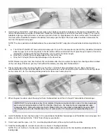
The die-cut Lite-Ply former F-2 has a dimple at the bottom to mark the correct position of the hole for the wing hold-down
dowel. Carefully drill at the dimple with a 1/4" drill bit. Use a chunk of hardwood behind the former to keep the wood from
splintering as you drill through.
31.
Glue the die-cut fuselage doublers to the die-cut fuselage sides using slow CA or Kwik-Set epoxy, and allow to dry. Be sure
to make one left side and one right side!
Содержание Four-Star 40 SIGRC44
Страница 1: ......